
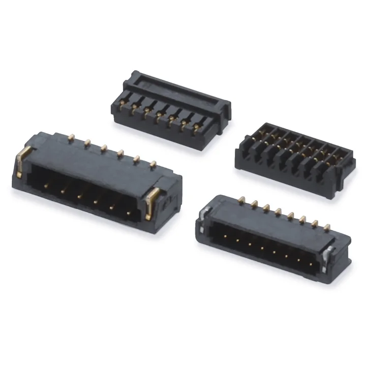
A0600 connector series
The housing table lists 2–16 positions; the drawing specifies LCP and gold-plated phosphor-bronze terminals.
Single-row housingSMT board connector
Product catalogue
Explore 132 products across connector systems, headers and custom cable assemblies. Compare the available details, then confirm your configuration against the released drawing before quotation.
Use the released drawing and required configuration to confirm suitability, commercial terms and compliance evidence.
Available technical details
Compare pitch, circuit range, orientation and PCB termination to select your connector series.
132 products shown
The housing table lists 2–16 positions; the drawing specifies LCP and gold-plated phosphor-bronze terminals.
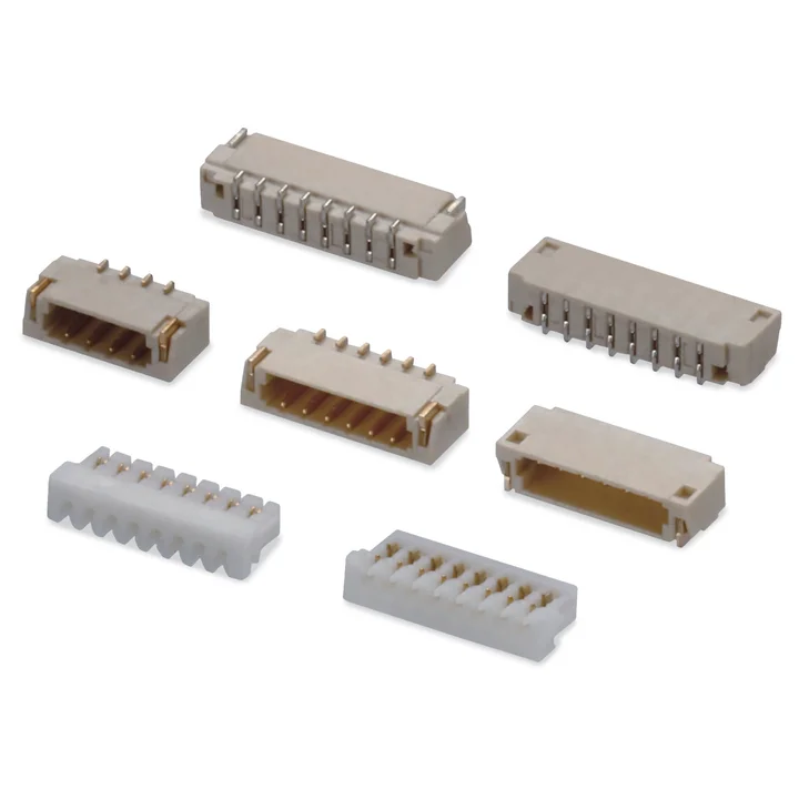
The A0800 housing drawing specifies PA66.
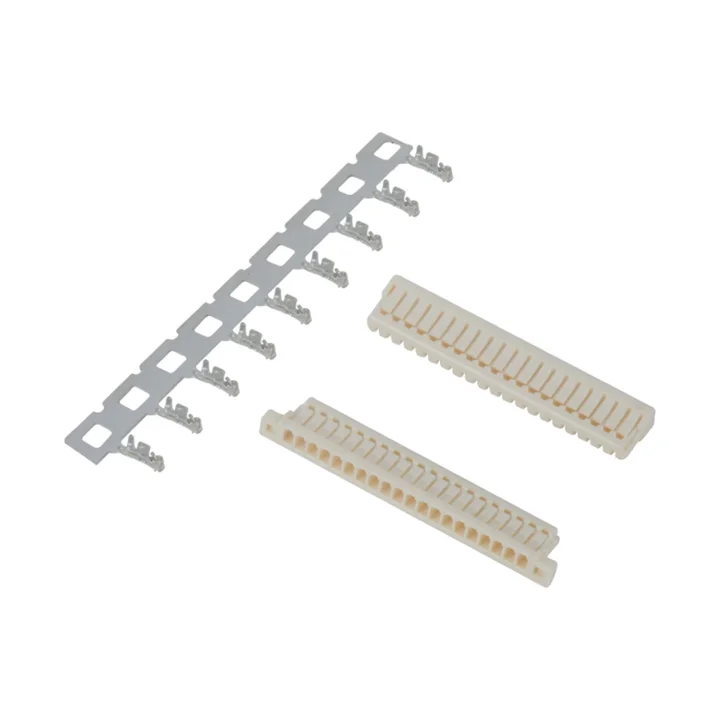
The two A0801 single-row housing tables each list 2–20 positions, with Nylon 46 bodies and different side features.
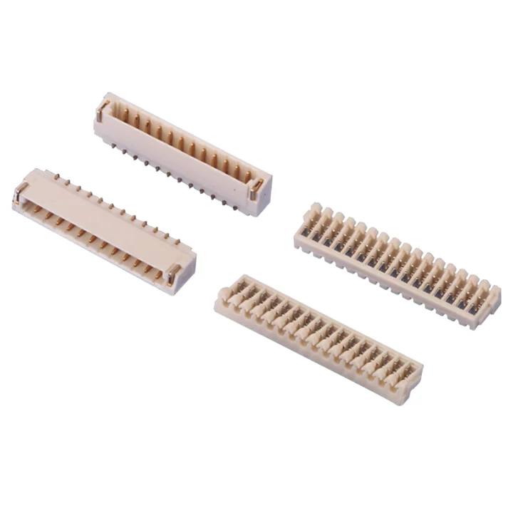
Both single-row housing tables list 2–20 positions and LCP bodies, with gold-plated or tin-plated phosphor-bronze terminals as specified for the selected configuration.
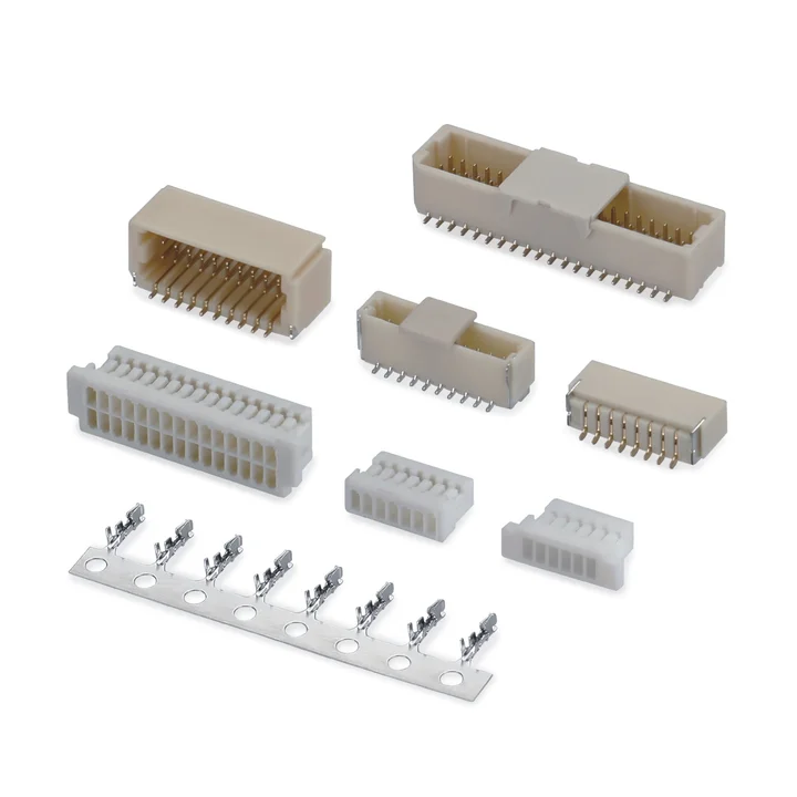
Wire-to-board connector system with crimp housings and SMT board connectors.
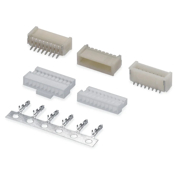
The housing table lists 2–20 positions and a Nylon 66 body, with different housing profiles shown.
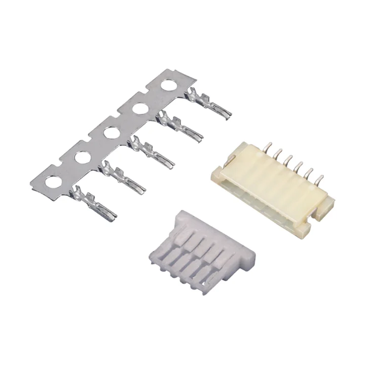
The drawing specifies a white Nylon 66 housing and a tin-plated phosphor-bronze crimp terminal.
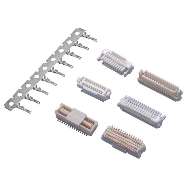
The housing table lists 20, 30, 40 and 50 total positions, with Nylon 66 bodies and two profiles shown.
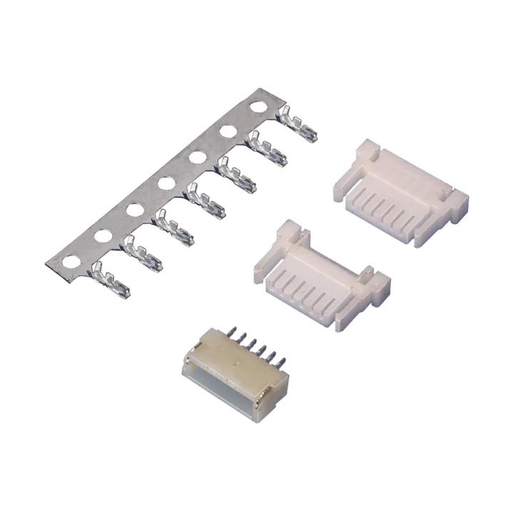
The housing table lists 2–20 positions with a white Nylon 66 body and a tin-plated phosphor-bronze terminal.
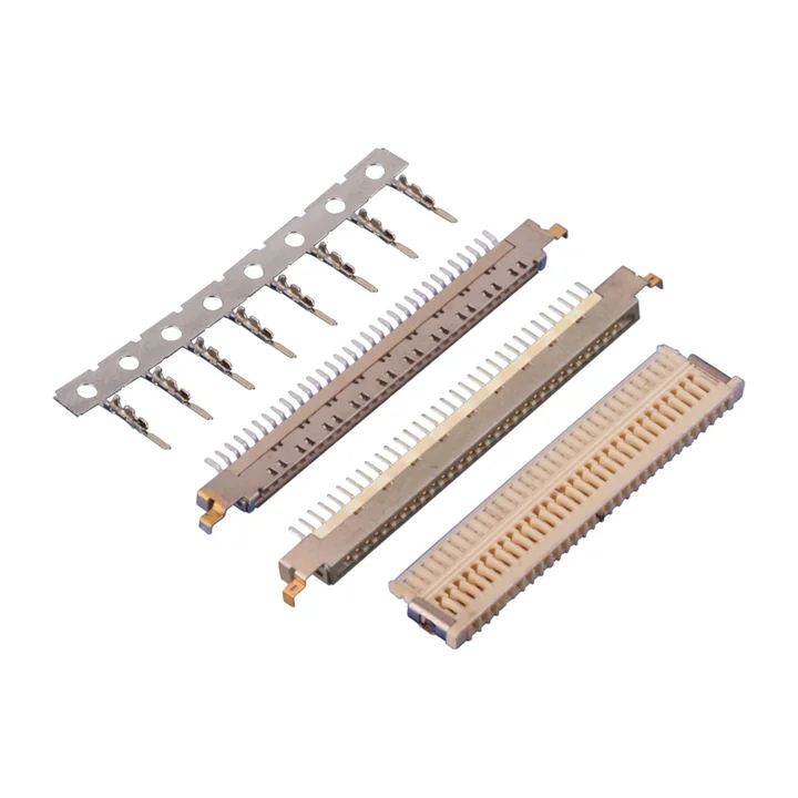
The A1006 housing table lists 20 and 30 positions and specifies PA46.
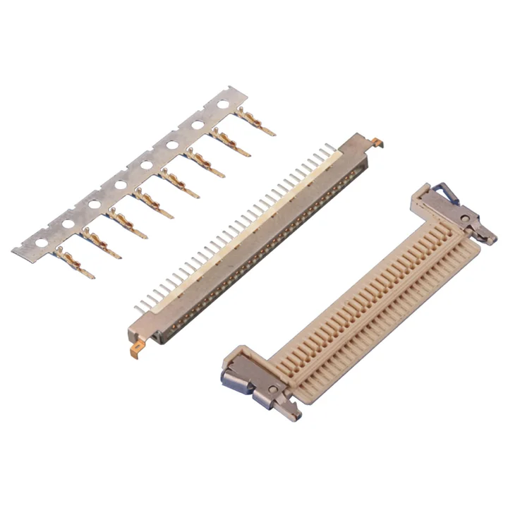
The A1008 housing drawing specifies Nylon 46 with a stainless-steel ground plate and a 1.00 mm contact pitch.
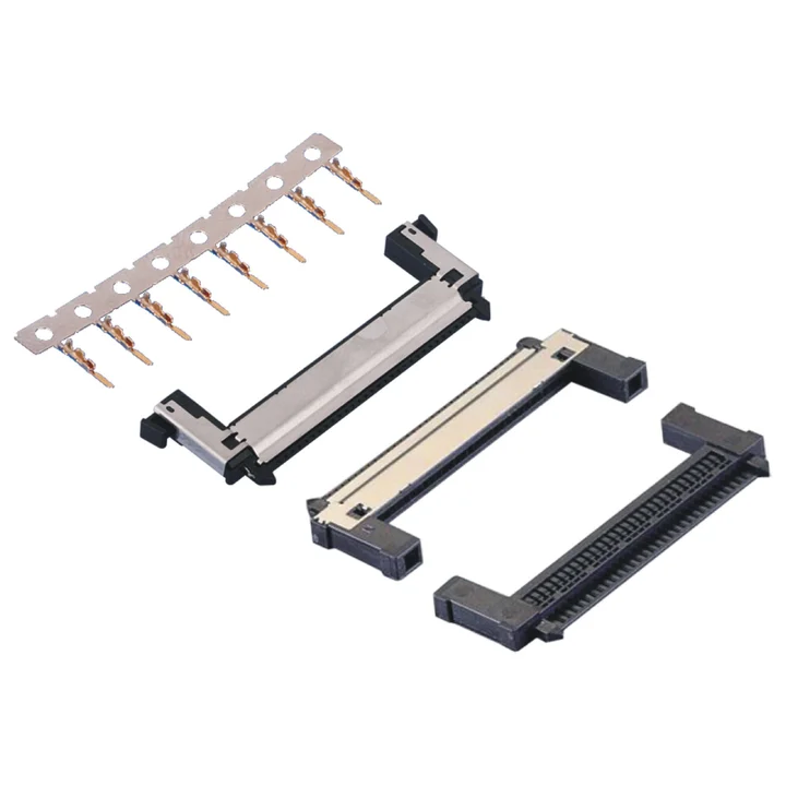
The housing drawings specify Nylon 46 and a stainless-steel ground plate.
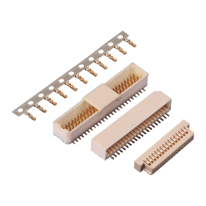
The Nylon 46 housing table lists 2 × 8, 2 × 10, 2 × 15, 2 × 20 and 2 × 25 positions.
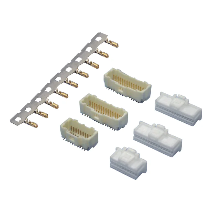
The housing table lists 2 × 2 through 2 × 20 positions and specifies Nylon 66.
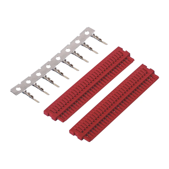
The A1015 housing drawing specifies a red Nylon 46 body and a 1.00 mm contact pitch.
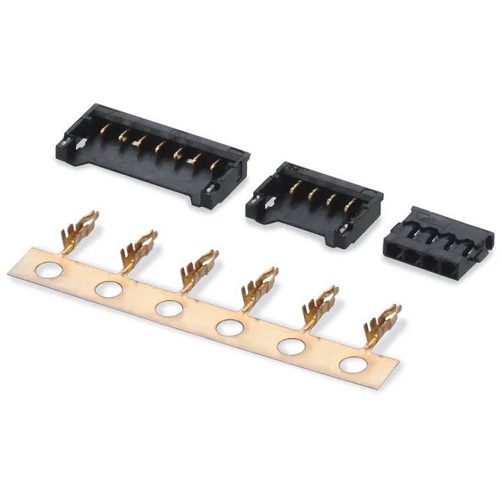
The housing table lists 2–15 positions and a black PA10T body.
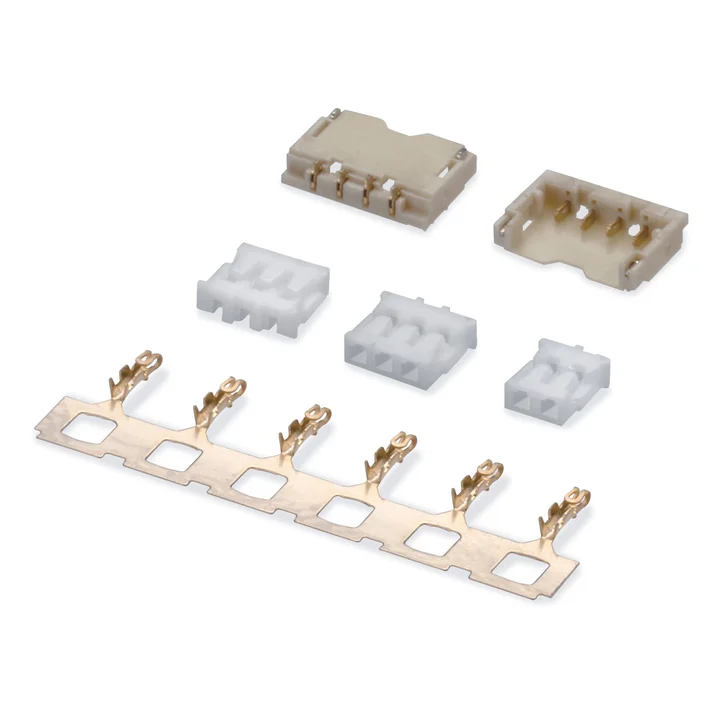
The housing table lists 1–15 positions and specifies PA66 in white or black.
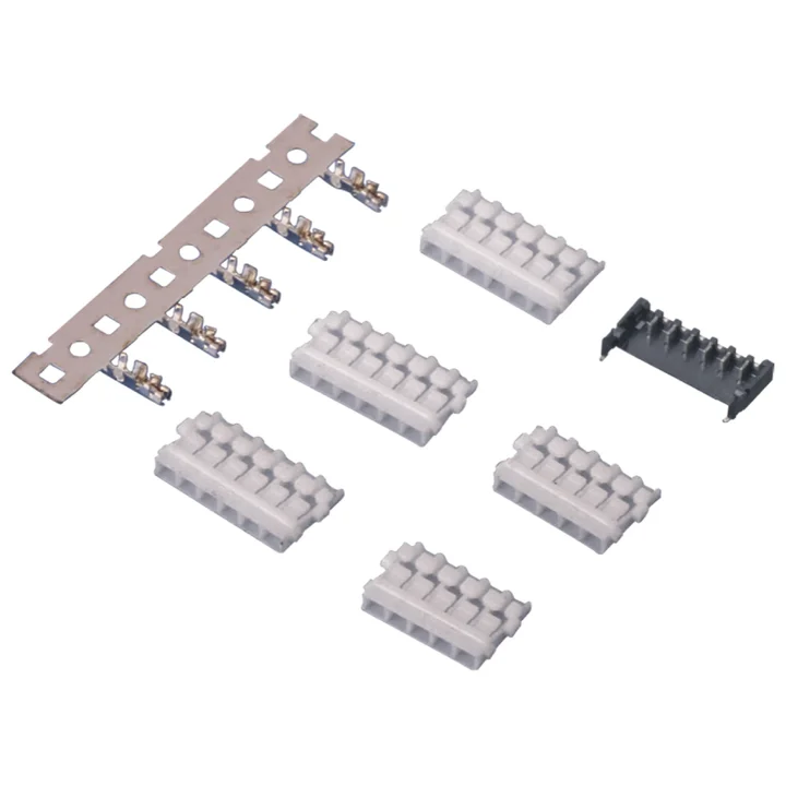
The housing table lists 2–6 positions and a white PBT body, with two housing profiles shown.
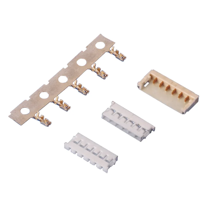
The housing table lists 2–9 positions and specifies PBT or PA66 body options for the selected configuration.
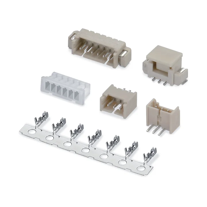
The female housing table lists 2–18 positions; the male housing table lists 2–15.
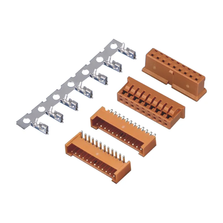
The housing table lists 2–15 positions and a brown PA66 body.
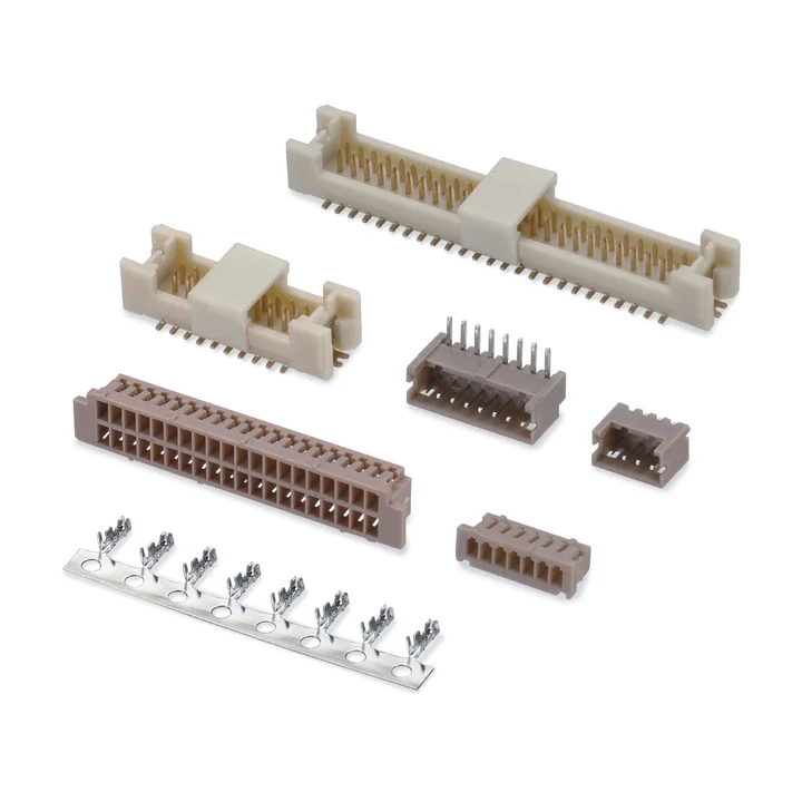
The single-row PA66 housing table lists 2–15 positions.
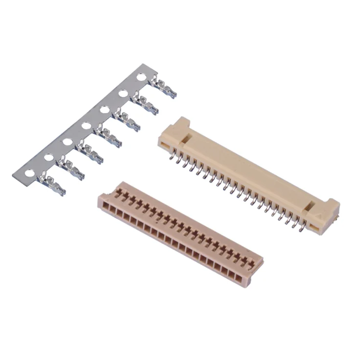
The two housing profiles specify PA66.
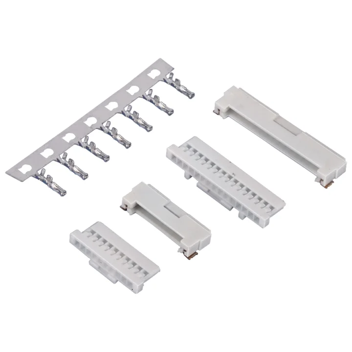
Construction details for this series are awaiting drawing confirmation.
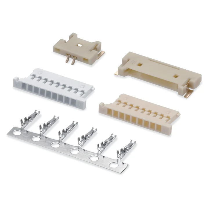
Two PA66 housing profiles are shown with different position tables and dimensions.
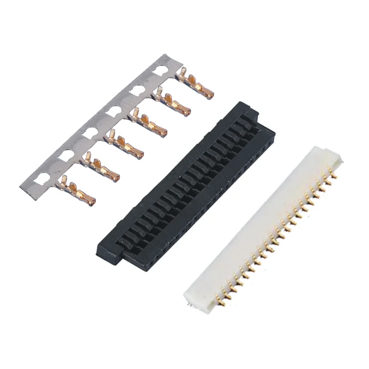
The black PA66 housing table lists 2–15, 20, 25 and 30 positions.
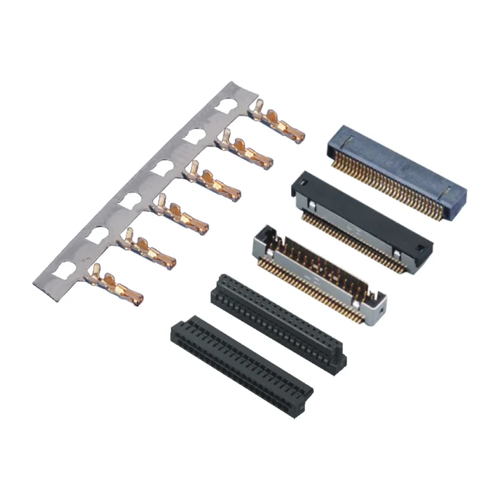
The drawings show PA66 housing profiles with staggered contacts and a tin-plated phosphor-bronze crimp terminal.
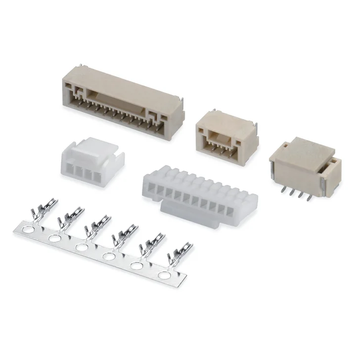
Single-row wire-to-board connector system with crimp housings and right-angle or vertical SMT board connectors.
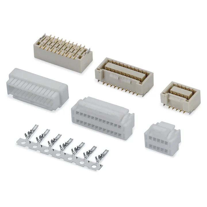
The PA66 housing table lists 2 × 5 through 2 × 16, then 2 × 18, 2 × 19 and 2 × 20.
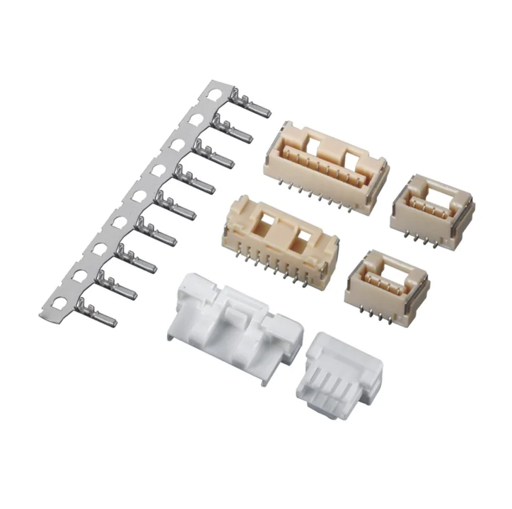
The PA66 housing table lists 2–15 positions, with different body features for smaller and larger configurations.
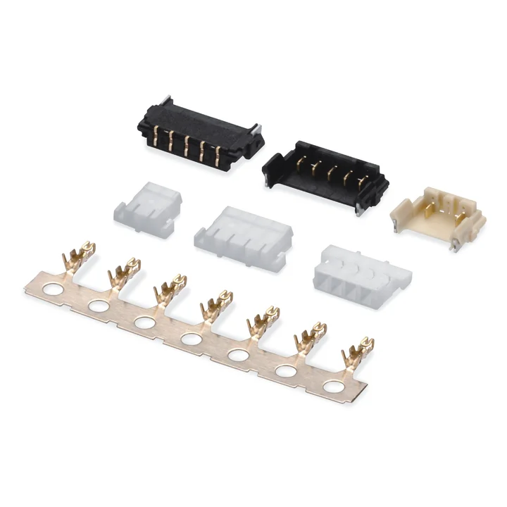
The PA66 housing table lists 2–12 positions in natural or black, with a distinct two-position profile.
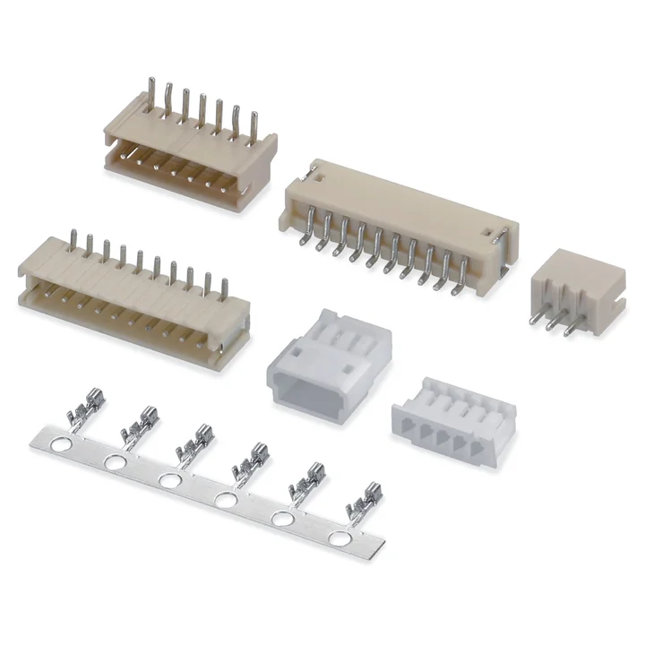
Single-row wire-to-board connector system with crimp housings and through-hole or SMT board connectors.
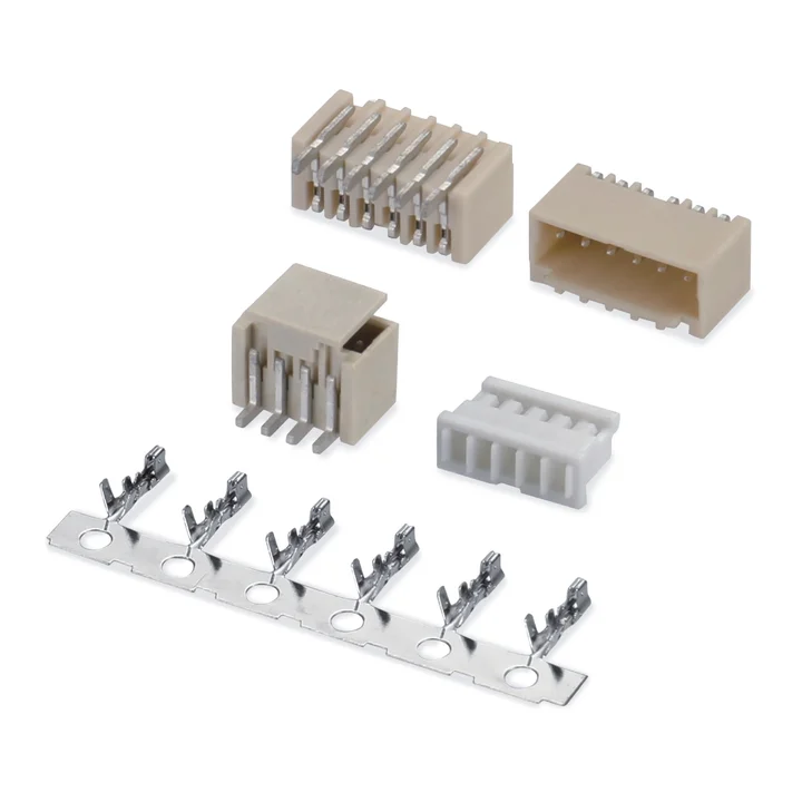
The housing table lists 2–15 positions and specifies PA66 or PBT body options.
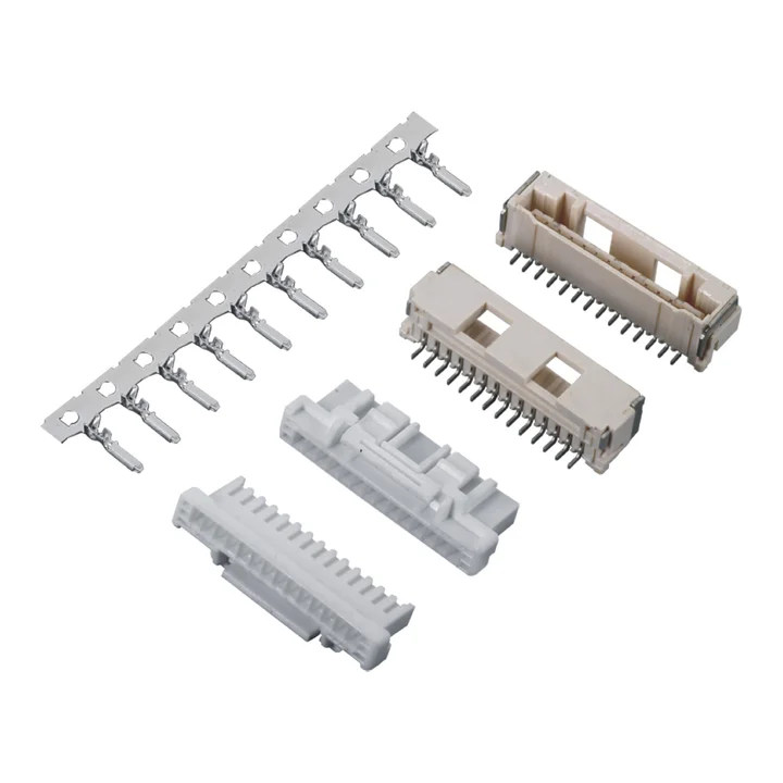
The PBT housing table lists 2–15 positions and shows size-specific latch and body profiles.
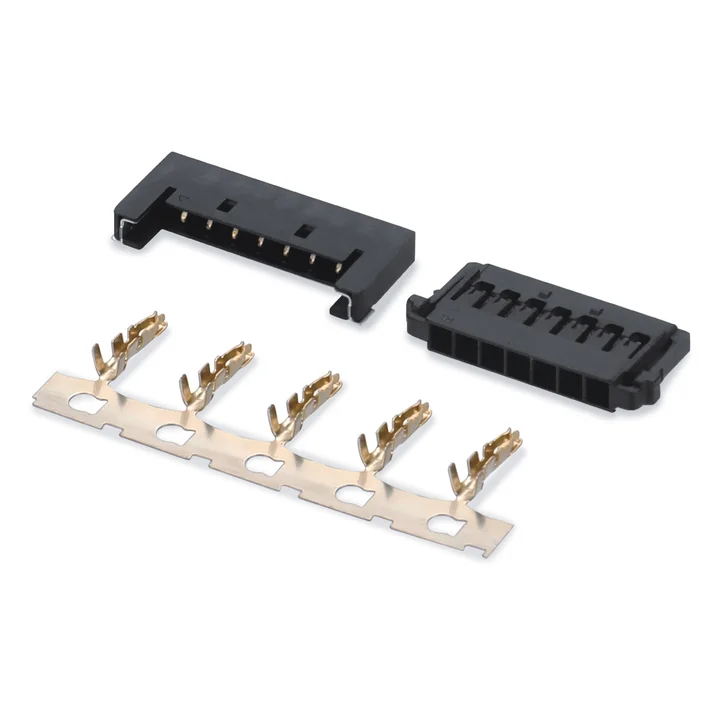
The housing table lists 4, 6, 8, 10 and 12 positions and a black PA66 body.
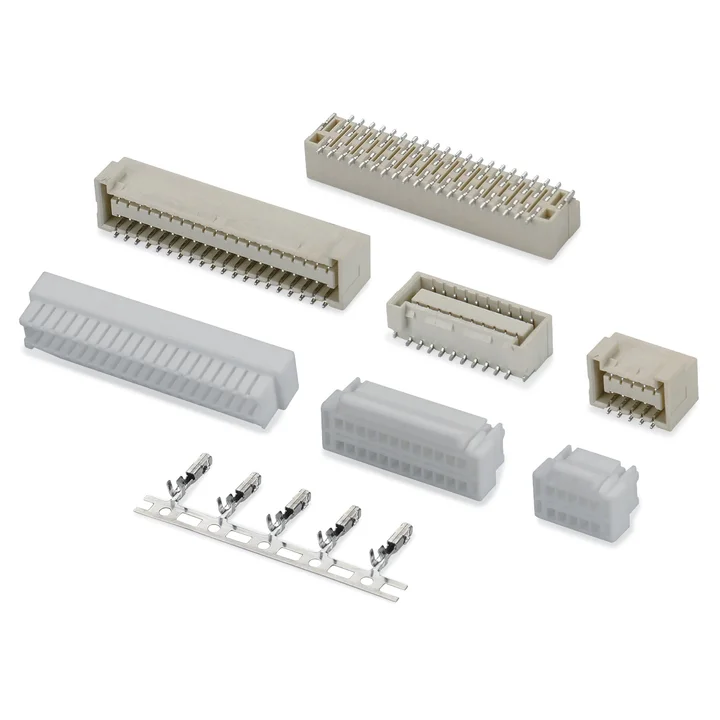
The PA66 housing table lists 2 × 5 through 2 × 20 positions with a tin-plated phosphor-bronze crimp terminal.
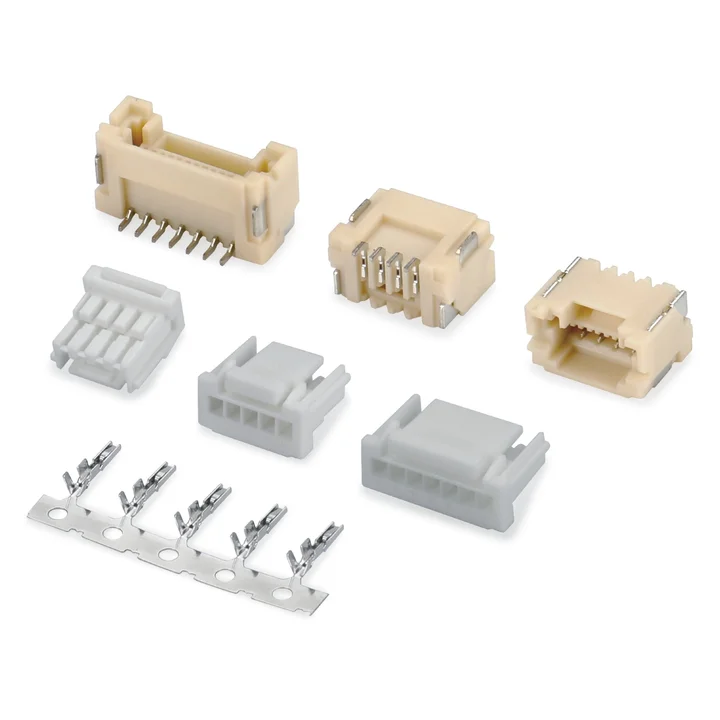
The PBT housing table lists 2–16 positions and size-specific body profiles.
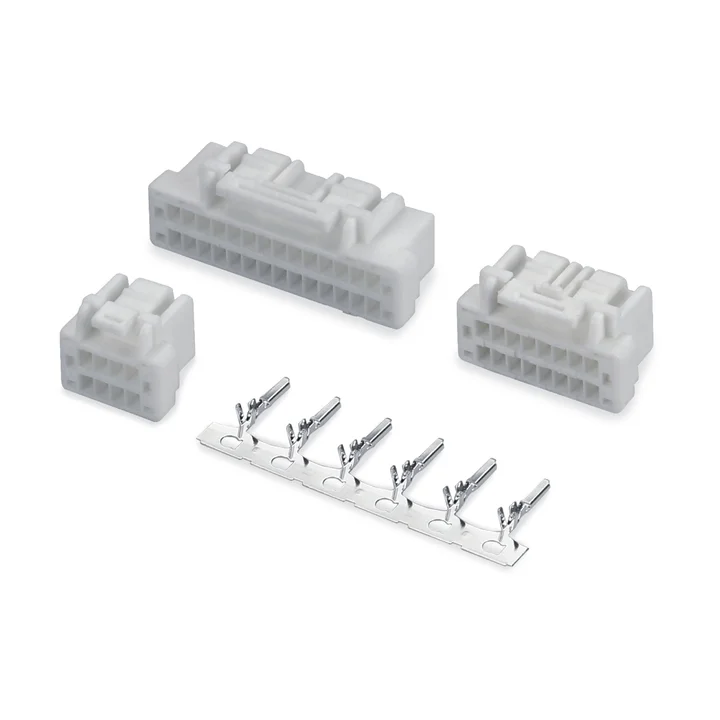
Construction details for this series are awaiting drawing confirmation.
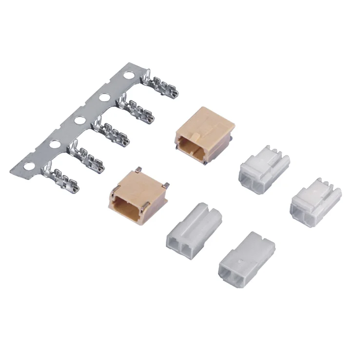
Both reviewed housing drawings are two-position single-row constructions with Nylon 66 bodies; the side and latch features differ.
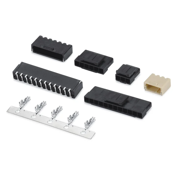
Construction details for this series are awaiting drawing confirmation.
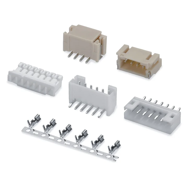
Single-row wire-to-board connector system with crimp housings and THT or SMT board connectors.
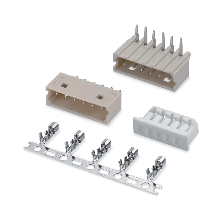
PA66 housing, tin-plated phosphor-bronze crimp terminal and straight or right-angle through-hole board connectors.
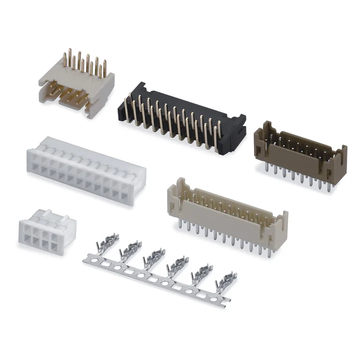
Three housing profiles and straight or right-angle through-hole board connectors are shown.
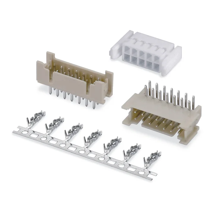
The side-latch housing drawing is paired with a tin-plated phosphor-bronze terminal and straight or right-angle through-hole board connectors.
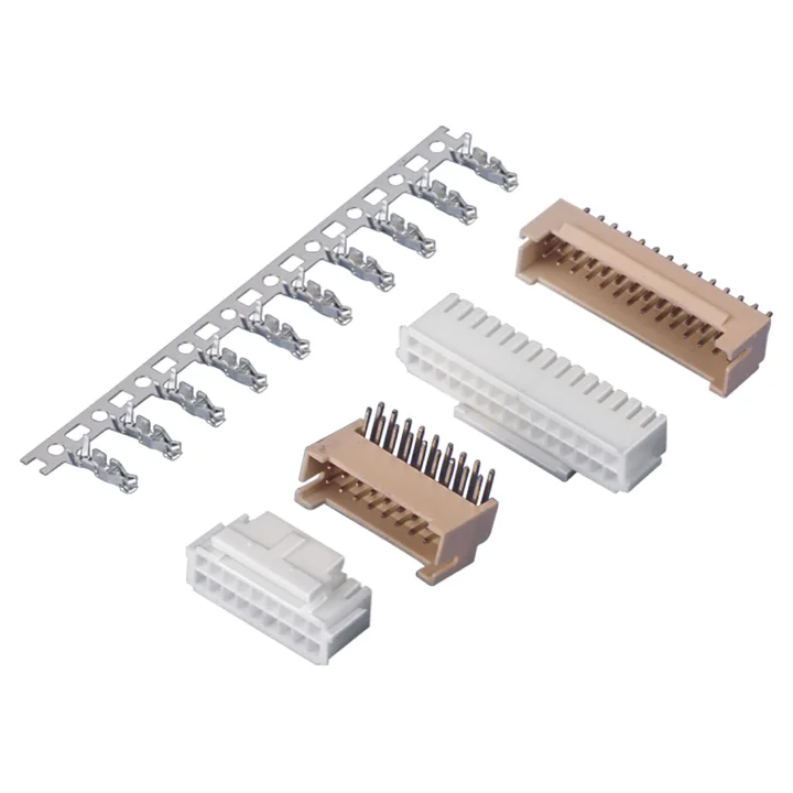
The supplied drawing set includes different housing heights and straight or right-angle through-hole board connectors.
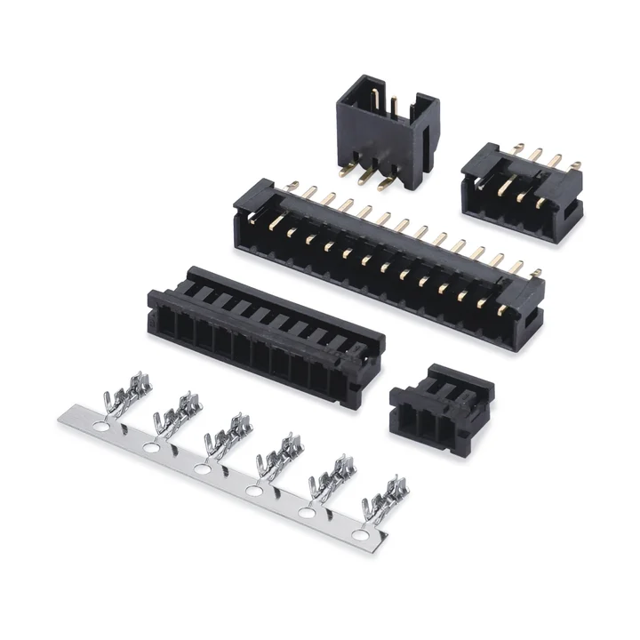
A black PA66 housing and tin-plated phosphor-bronze terminal pair with PA6T through-hole board connectors.
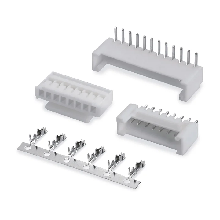
PA66 housing, a tin-plated phosphor-bronze terminal, and straight or right-angle through-hole board connectors are shown.
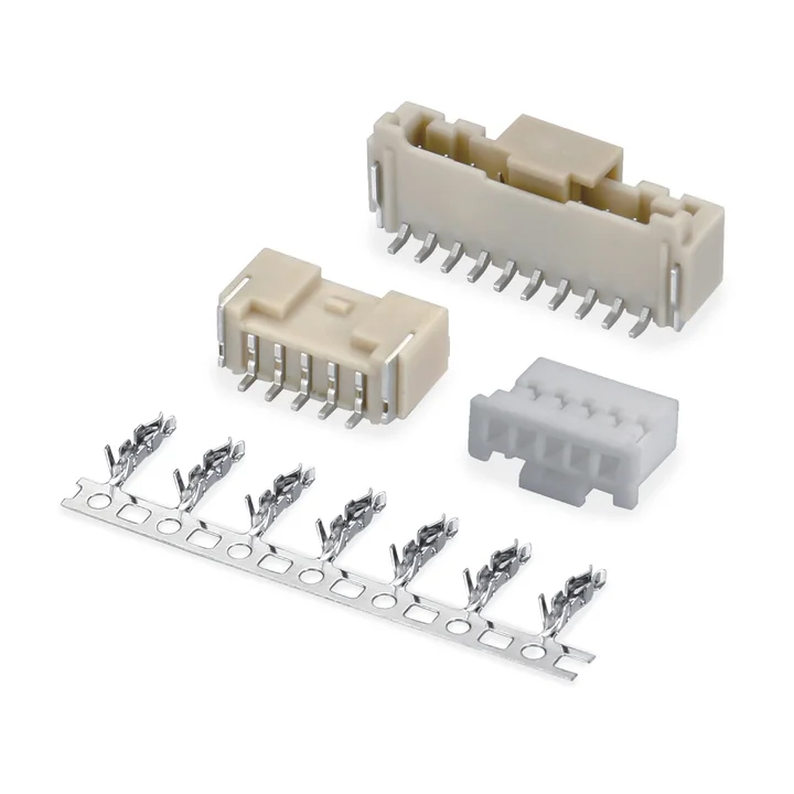
The single-row PA66 housing is shown with PA9T board connectors in straight and right-angle through-hole versions, plus SMT versions with solder tabs.
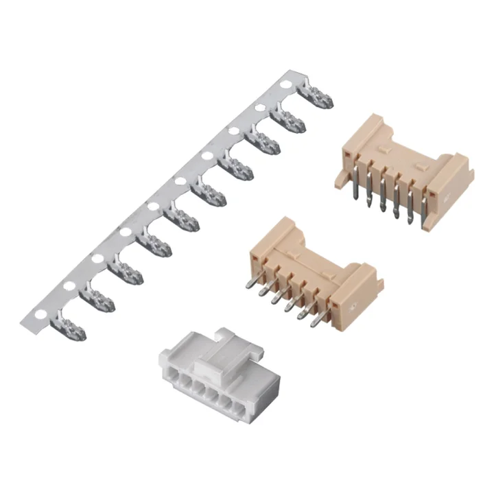
PA66 housing, a tin-plated phosphor-bronze terminal and two through-hole board profiles are documented.
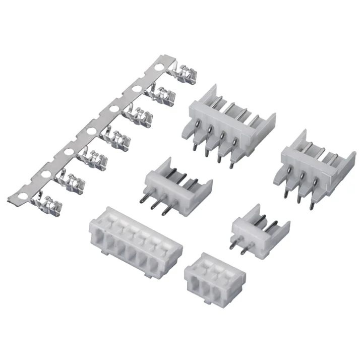
A PA66 housing and tin-plated phosphor-bronze terminal are shown with straight and right-angle PA66 through-hole board connectors.
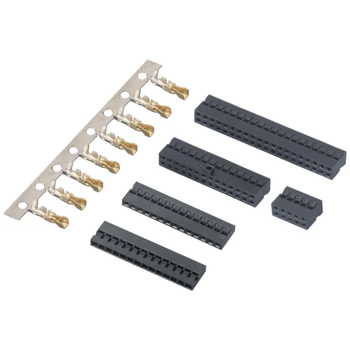
Two single-row black PA66 housing profiles and separate terminal designs are documented.
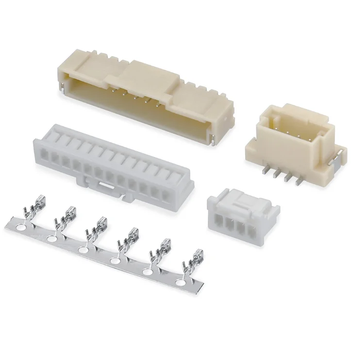
The housing drawing lists PA66 or PBT, while the two SMT board profiles use PA9T.
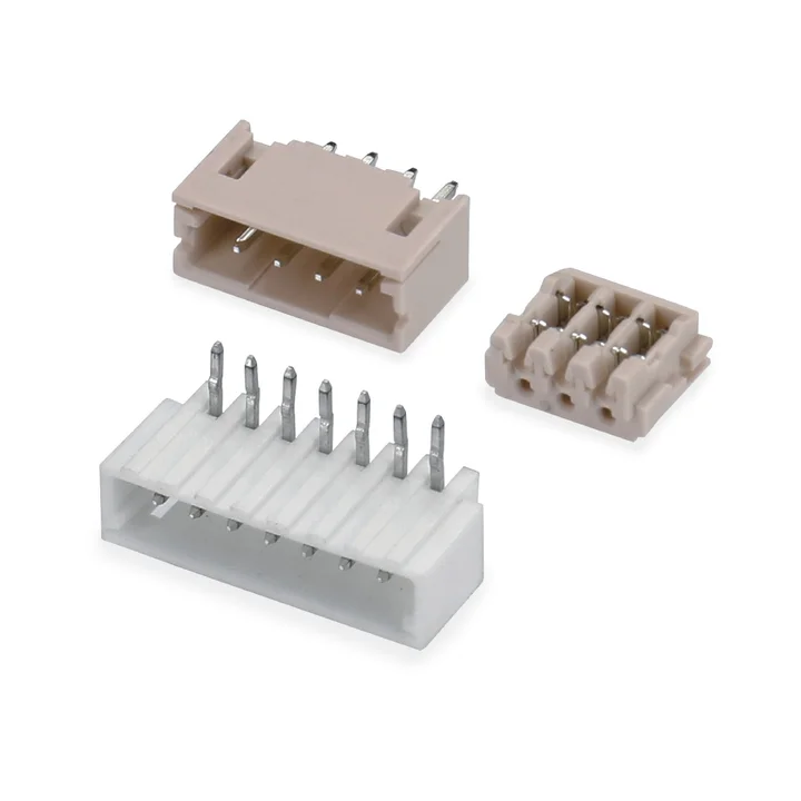
The housing and straight through-hole board variant use glass-filled PA66; the right-angle board variant uses glass-filled PBT.
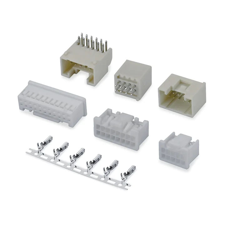
Construction details for this series are awaiting drawing confirmation.
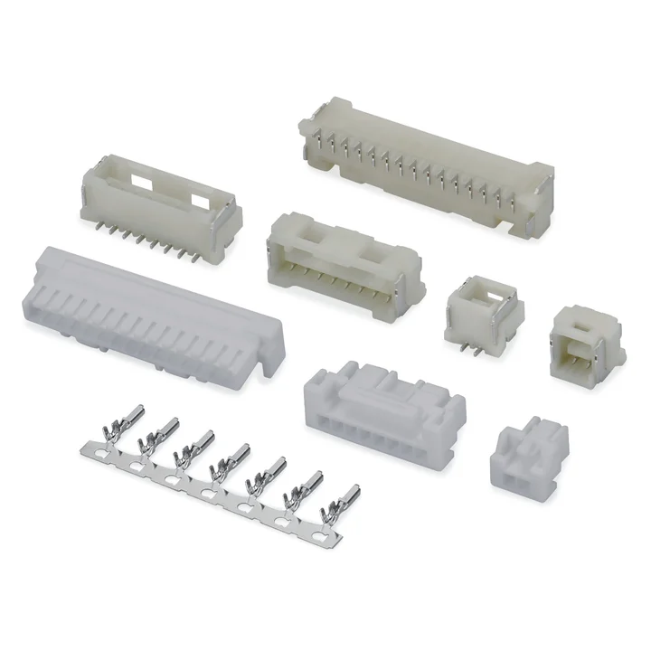
Construction details for this series are awaiting drawing confirmation.
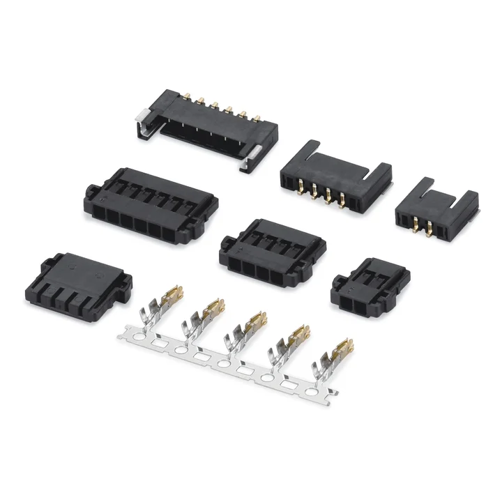
Construction details for this series are awaiting drawing confirmation.
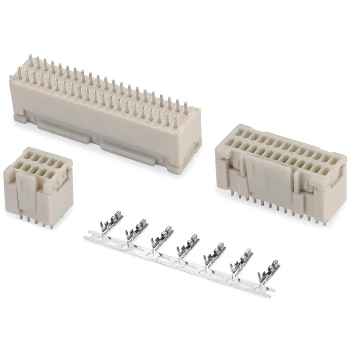
Construction details for this series are awaiting drawing confirmation.
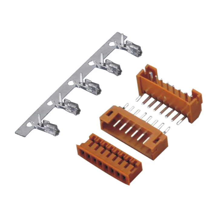
Brown PA66 housing and straight or right-angle PA66 board connectors are documented.
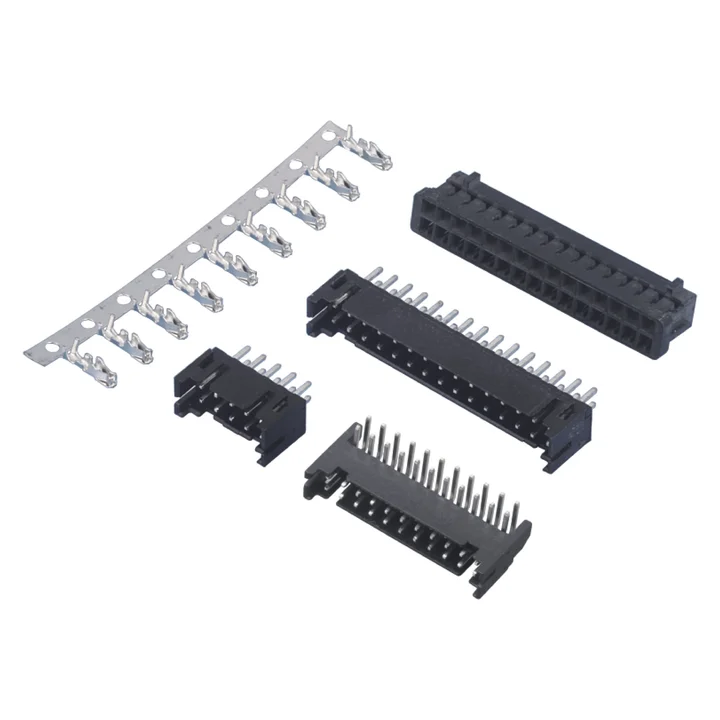
Black PA66 housing and straight or right-angle through-hole board connectors are shown, together with a separate PA6T SMT board profile.
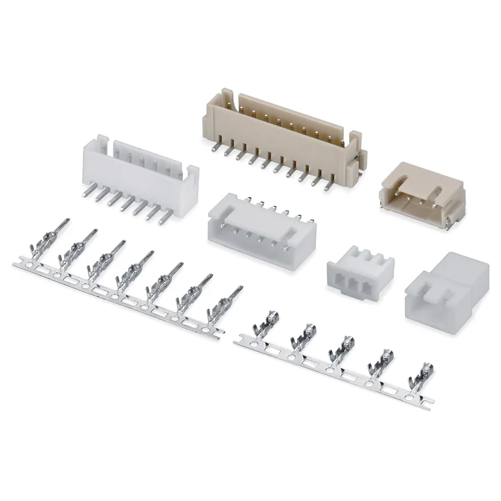
Single-row connector system with crimp housings, male and female terminals, and THT or right-angle SMT board connectors.
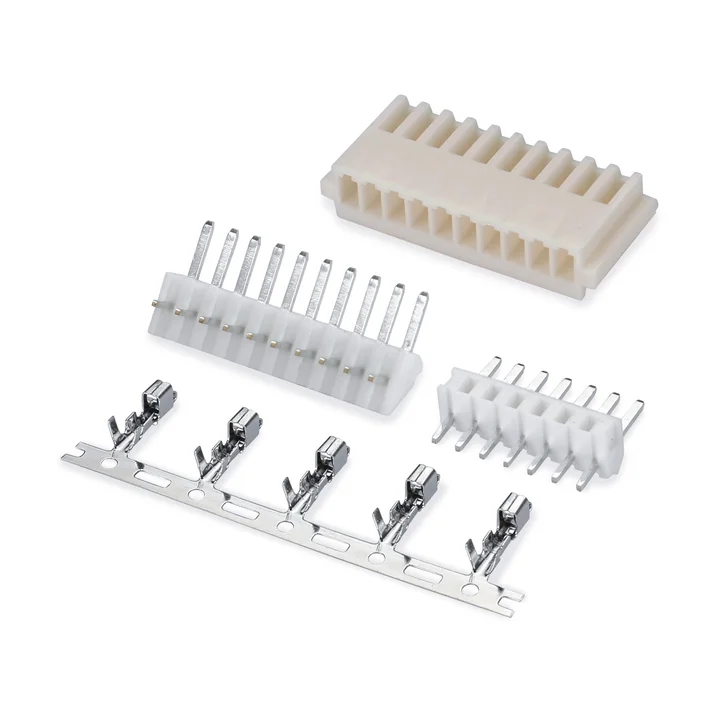
The PA66 housing is explicitly identified as the HB profile.
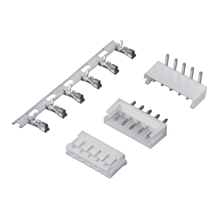
White PA66 housing and straight or right-angle PA66 through-hole board connectors are documented.
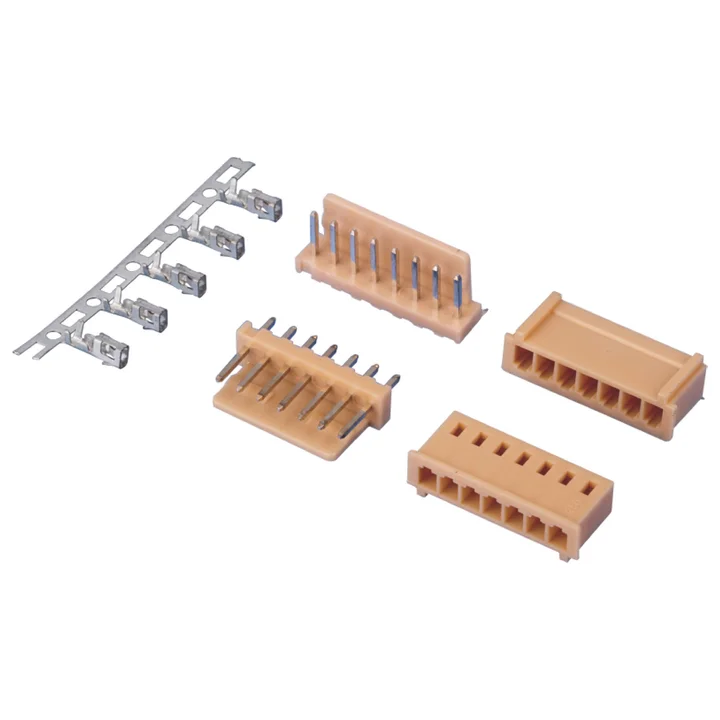
Natural PA66 housing and straight or right-angle PA66 through-hole board connectors are shown with a tin-plated phosphor-bronze crimp terminal.
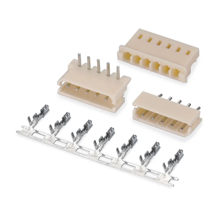
Natural PA66 housing and straight or right-angle PA66 through-hole board connectors are shown with a tin-plated phosphor-bronze terminal.
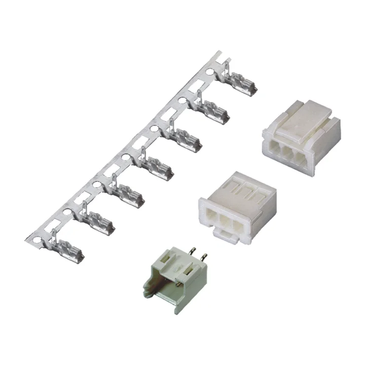
A white PA66 housing is documented with a crimp terminal and a natural PA66 straight through-hole board connector; the terminal and board pins are tin-plated phosphor bronze.
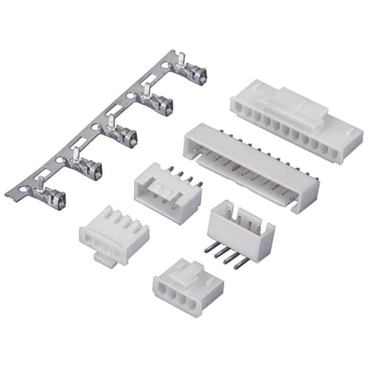
The reviewed white PA66 housing is the B profile.
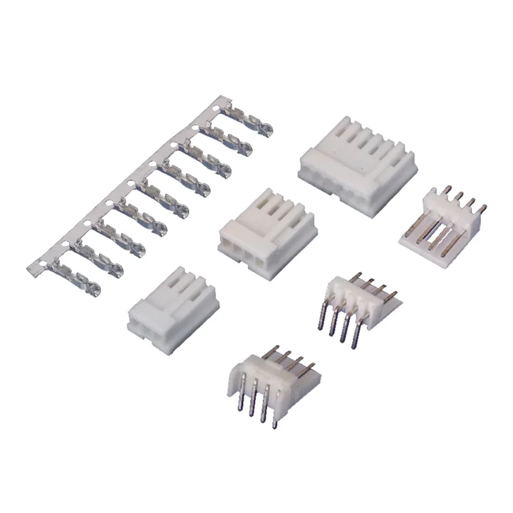
The drawing specifies 2.50 mm pitch despite the series code.
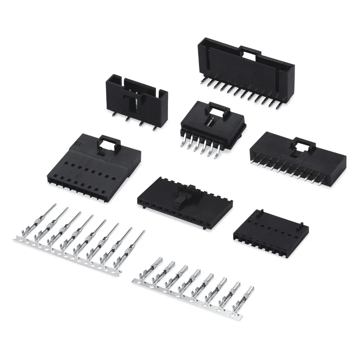
Separate male and female PA66 housing profiles are documented, with straight and right-angle through-hole and SMT board variants.
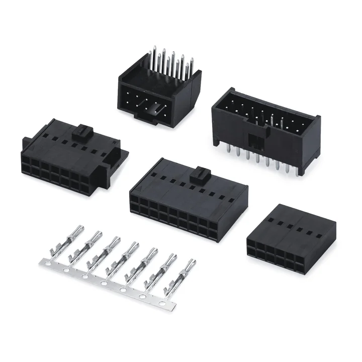
The HA housing is explicitly identified as a black PBT dual-row profile.
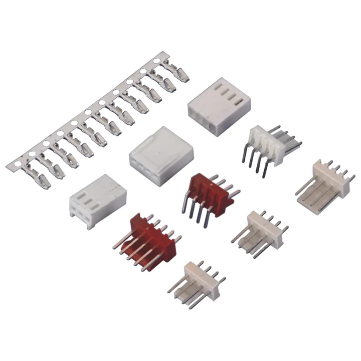
Two PA66 housing profiles and several straight or right-angle PA66 through-hole board connector profiles are documented.
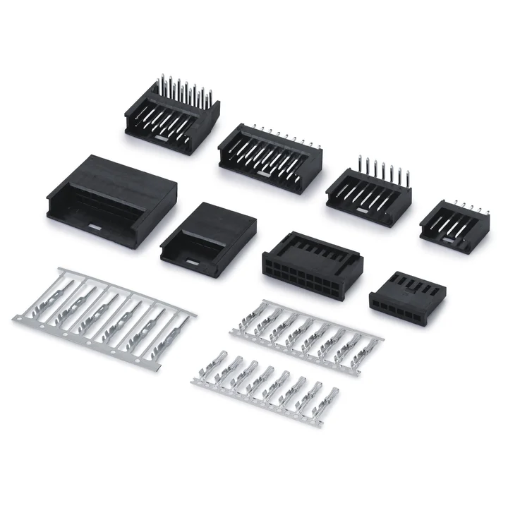
Separate male and female housings are documented in single-row and dual-row layouts, together with multiple through-hole board profiles.
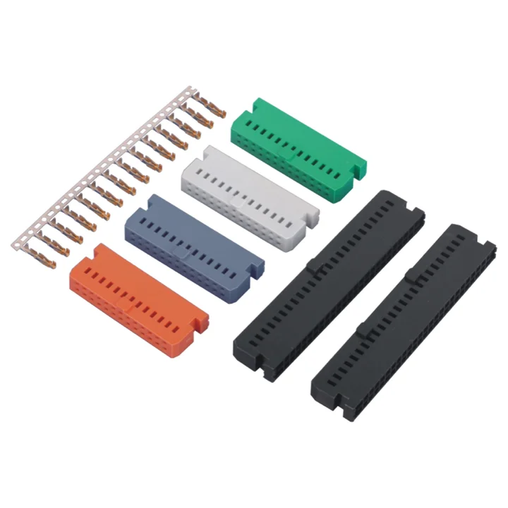
Dual-row wire-to-board connector system with crimp housings and ejector-latch board connectors.
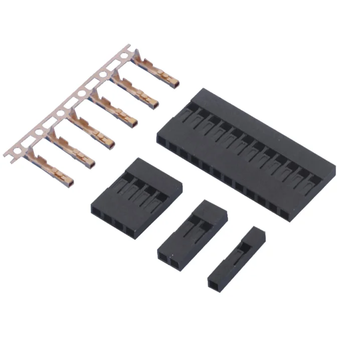
Black PPO housing with separately documented female and male crimp terminals.
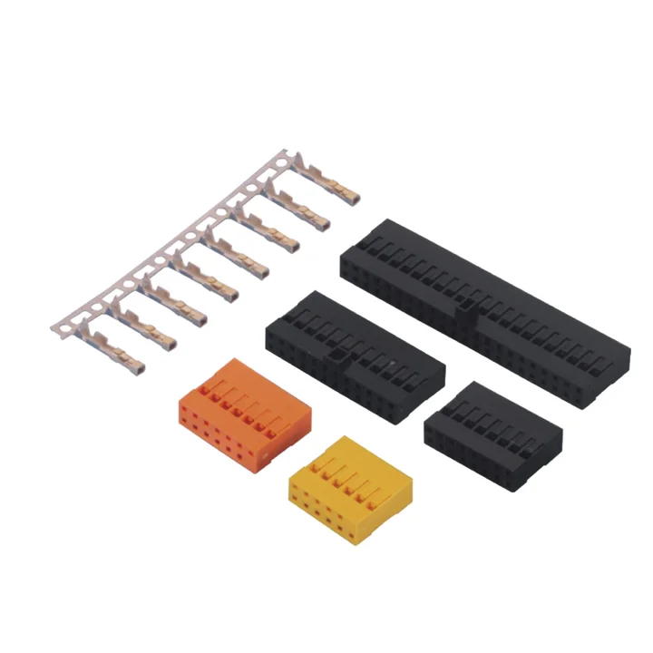
Black PPO standard and alternate-lock housings list 2×2 to 2×40 positions; the other latch profile lists 2×2 to 2×20.
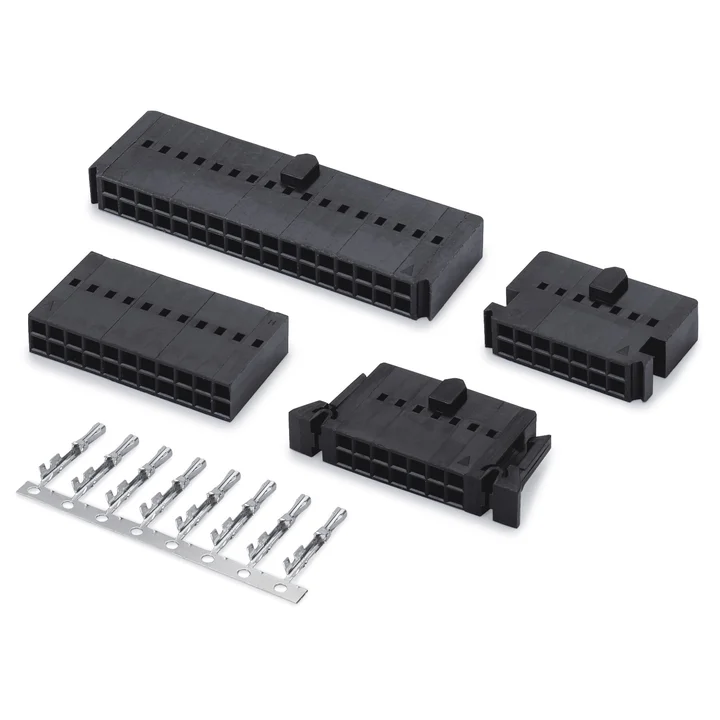
Black PBT housings have several latch, key and mounting profiles.
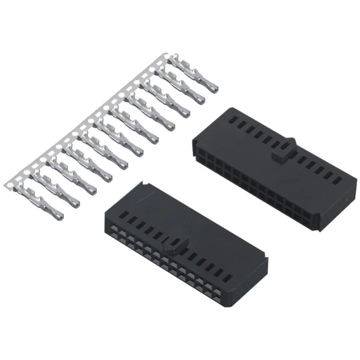
A black PA66 dual-row housing and a tin-plated phosphor-bronze terminal are documented.
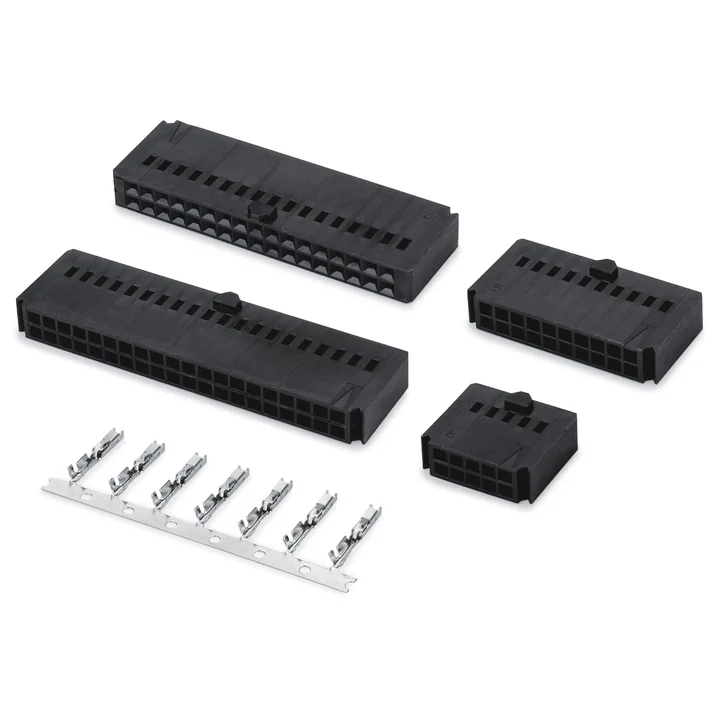
The housing drawing specifies black PA66 and selected dual-row position counts.
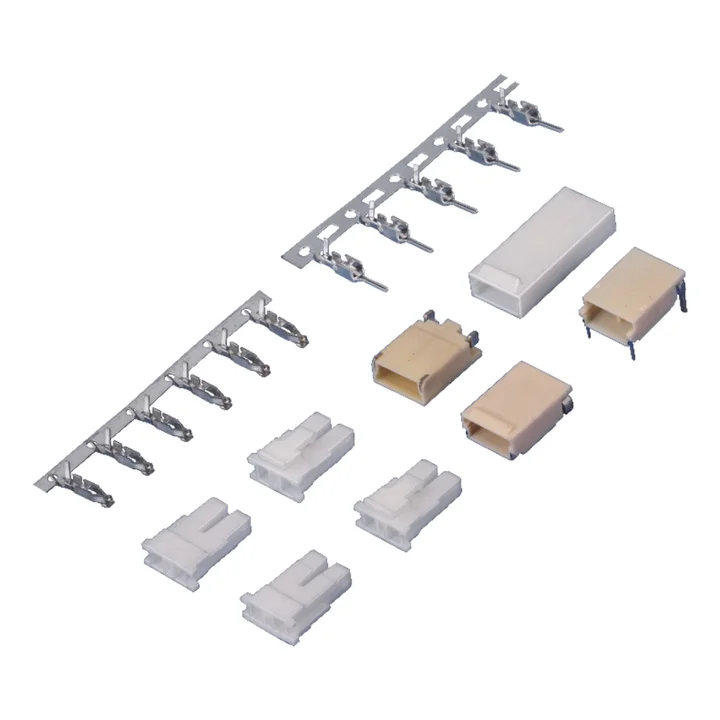
Natural PA66 male and female cable housings are documented with tin-plated phosphor-bronze terminals.
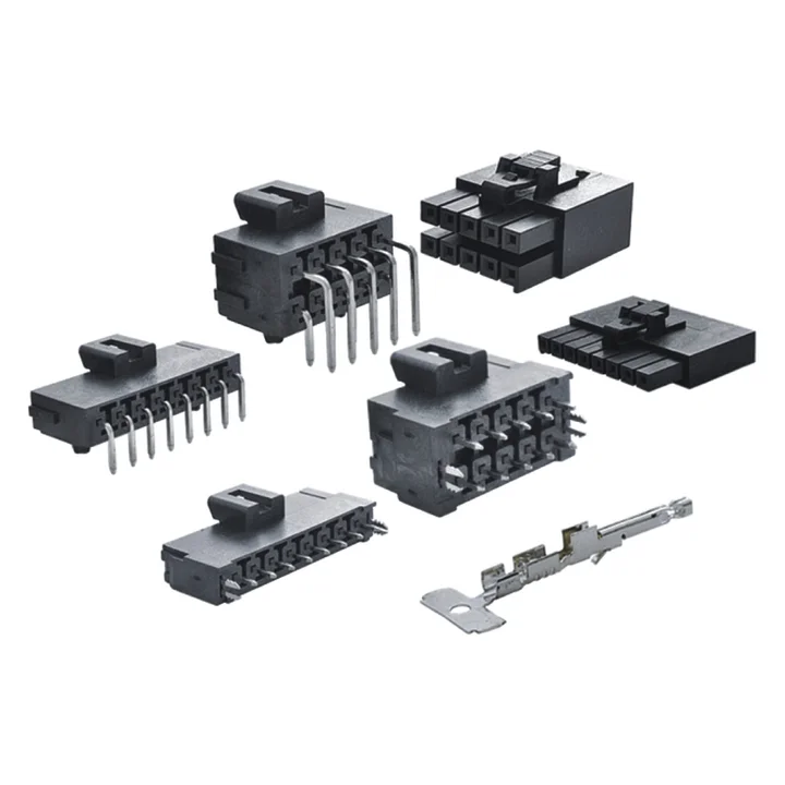
Black PA4T housings include standard and terminal-position-assurance profiles.
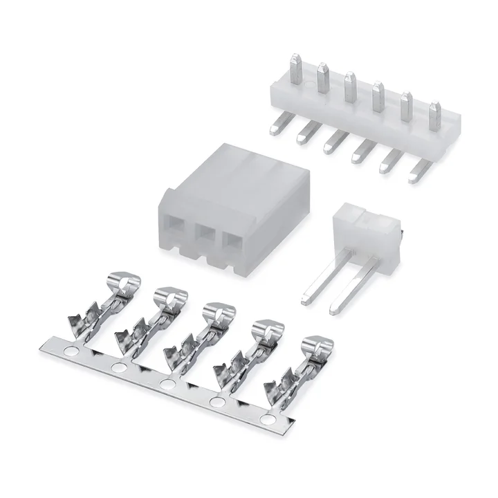
Natural PA66 housings are shown with straight and right-angle PA66 through-hole board profiles.
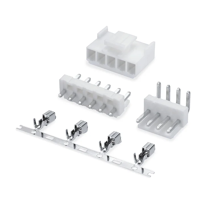
Single-row wire-to-board connector system with crimp housings and right-angle or vertical through-hole board connectors.
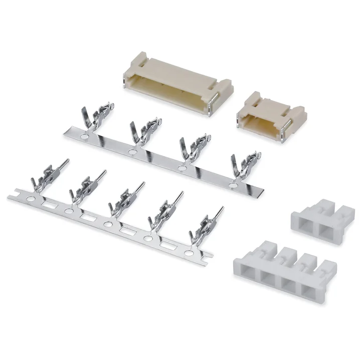
White PA66 male and female housings are documented with tin-plated phosphor-bronze terminals.
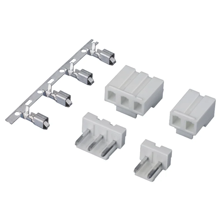
Natural PA66 housing, a tin-plated phosphor-bronze crimp terminal and a natural PA66 straight through-hole board profile are documented.
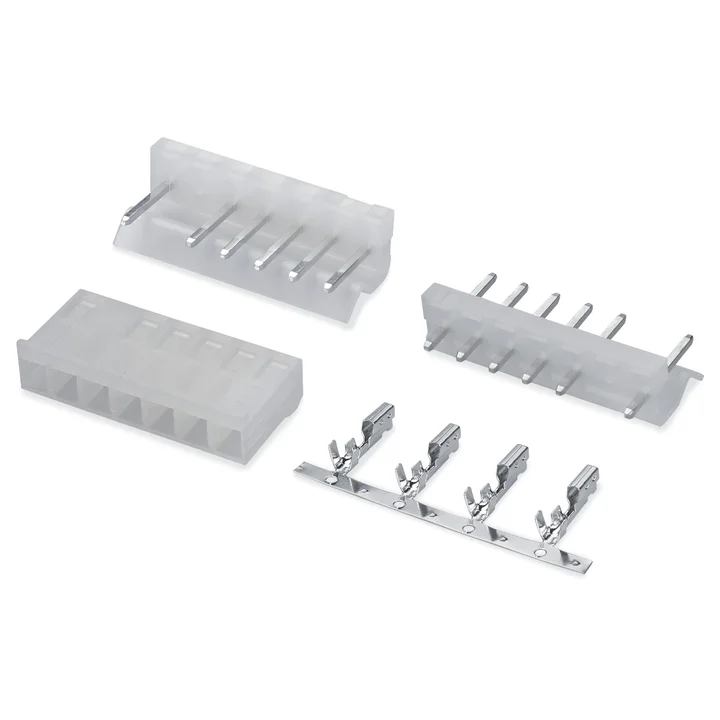
Construction details for this series are awaiting drawing confirmation.
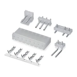
The reviewed housing specifies natural PA66.
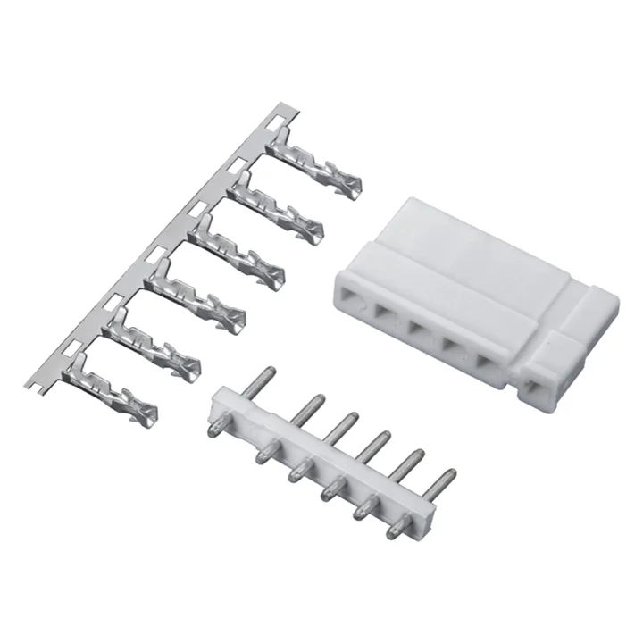
Construction details for this series are awaiting drawing confirmation.
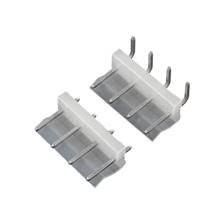
Construction details for this series are awaiting drawing confirmation.
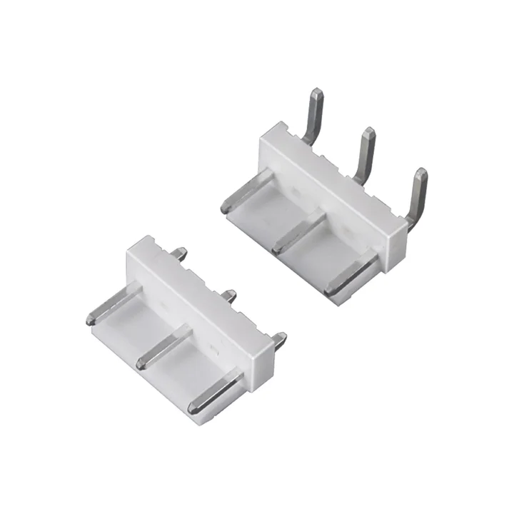
Construction details for this series are awaiting drawing confirmation.
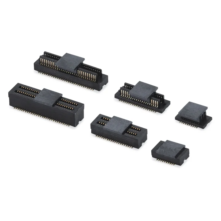
Construction details for this series are awaiting drawing confirmation.
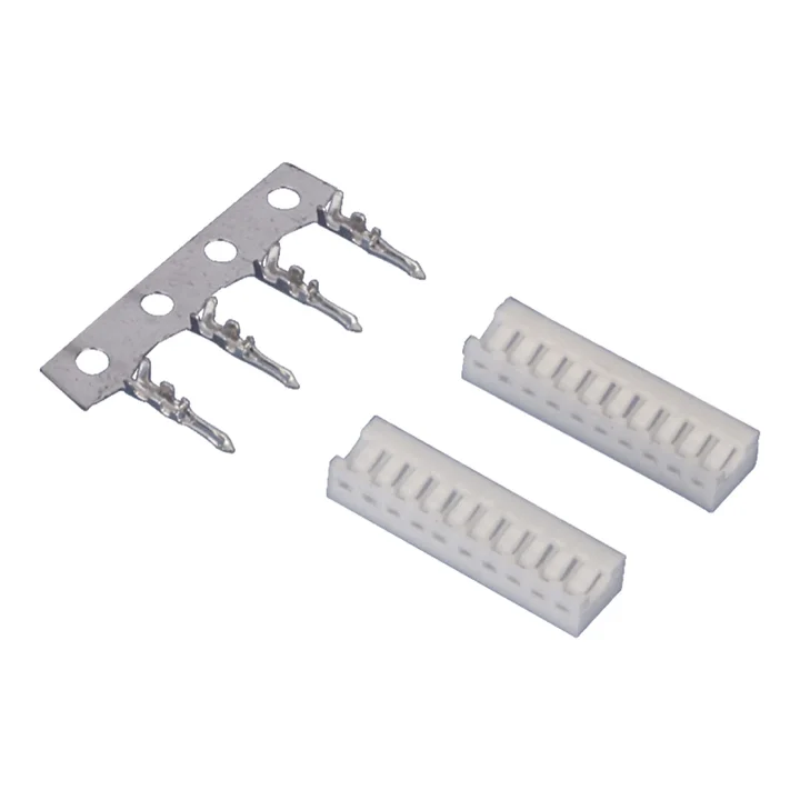
PA66 housing with wire terminals for PCB termination; the housing table lists 2–15 positions.
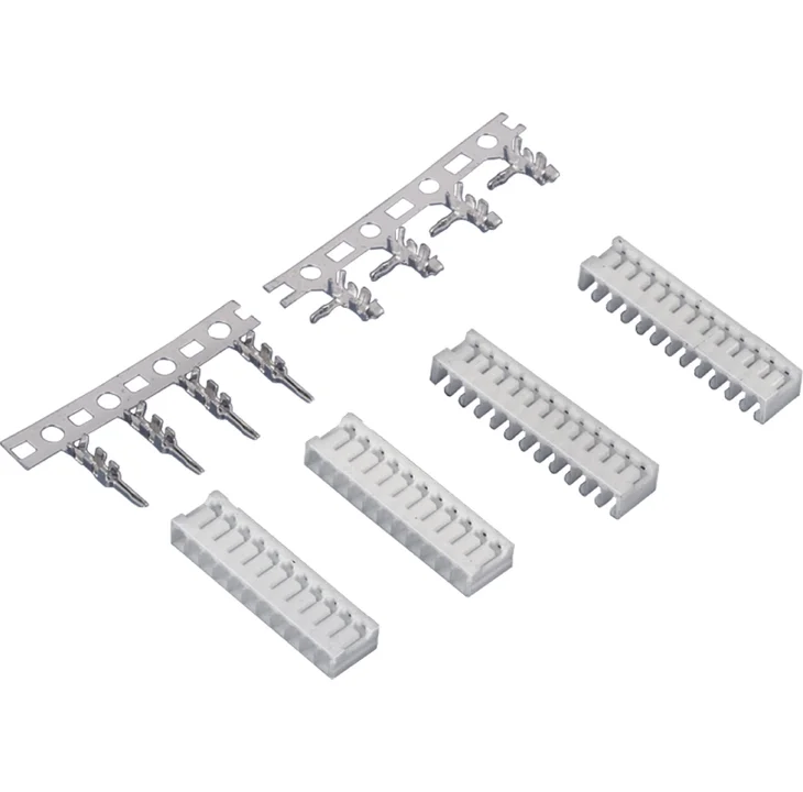
Single-row board-in housings in two PA66 profiles, with 2-14 positions. Terminal selection depends on the required housing profile.
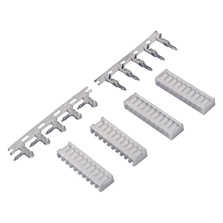
Single-row PA66 housings in two profiles, with 2–16 positions listed in the reviewed housing tables.
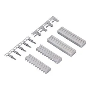
Single-row PA66 housings; one profile lists 2–15 positions and another lists 2–16.
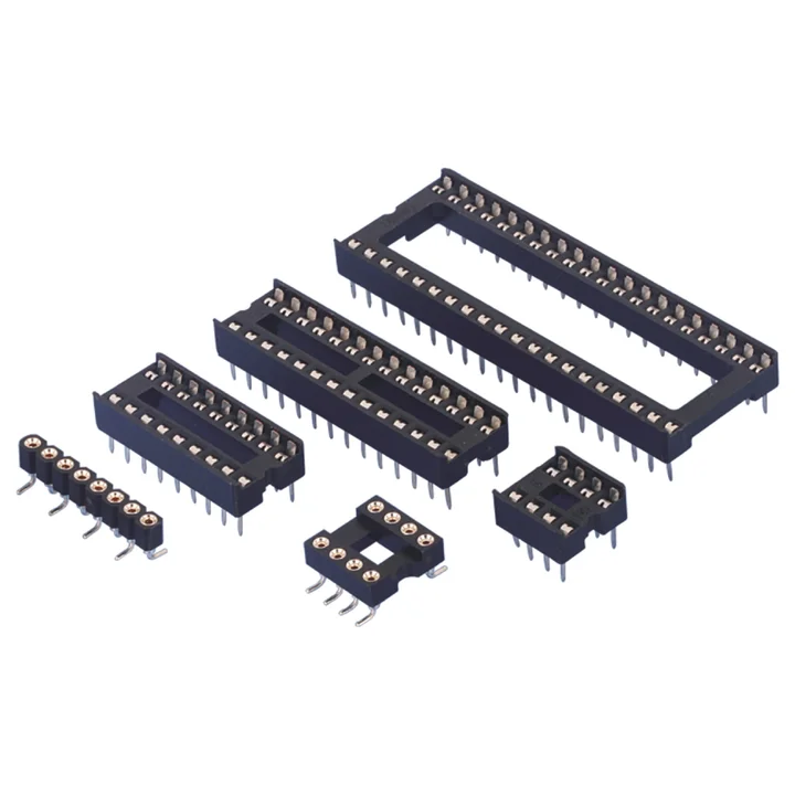
Single-row and dual-row IC socket constructions, with through-hole and surface-mount variants.
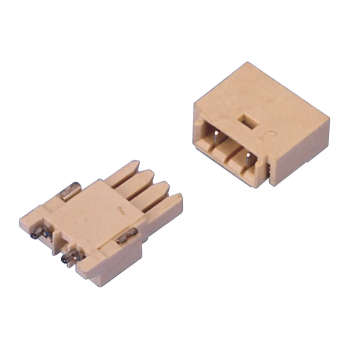
The reviewed mating pair has two positions and right-angle surface-mount construction, with LCP housings and tin-plated phosphor-bronze contacts.
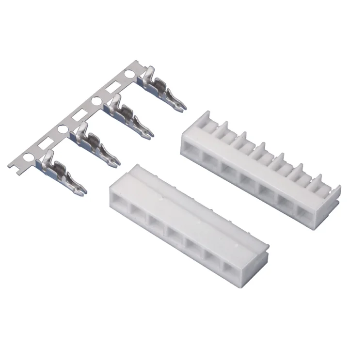
Single-row PA66 housings in two profiles, with 2–15 positions listed.
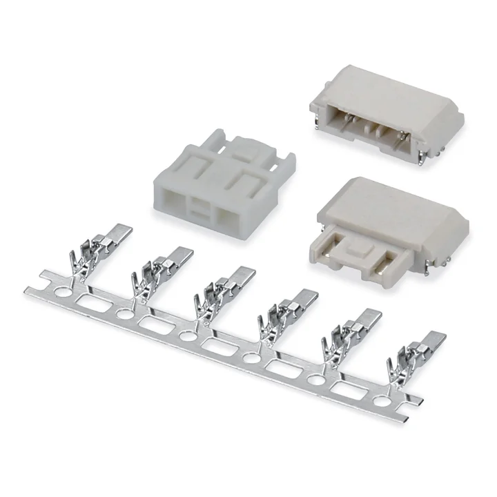
PBT housings with one- and two-position examples; the reviewed two-position surface-mount PCB pair specifies LCP housings and tin-plated phosphor-bronze contacts.
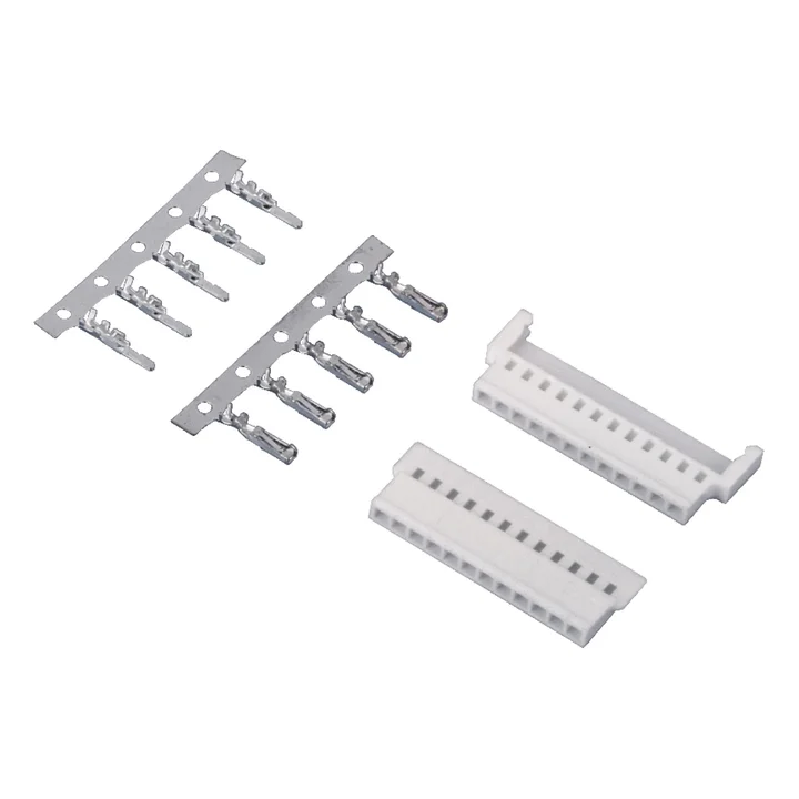
Single-row PBT male and female housings; the tables list 2–11 and 13 positions.
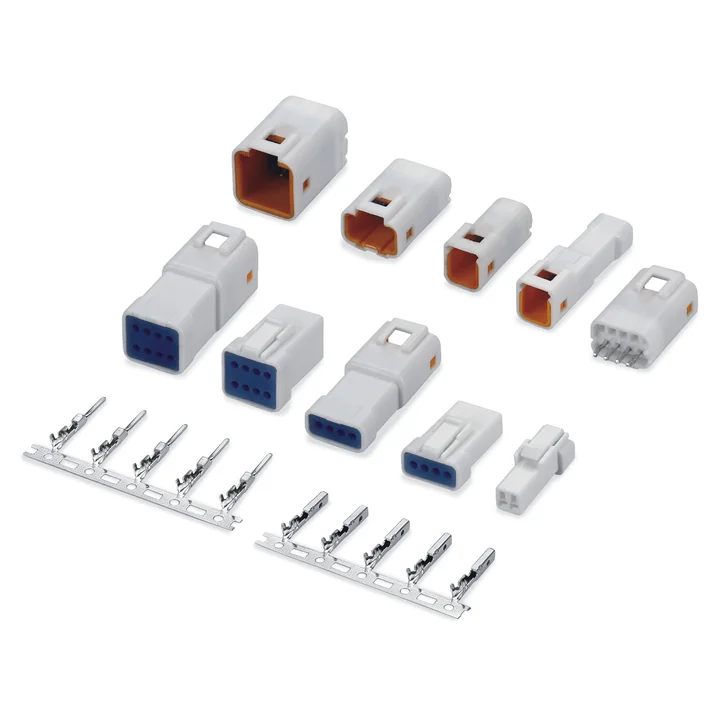
Construction details for this series are awaiting drawing confirmation.
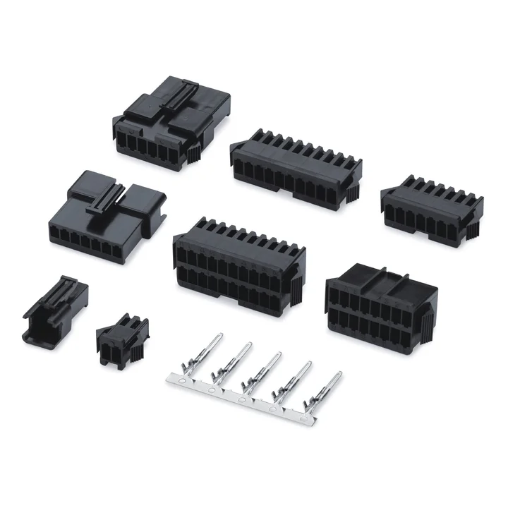
Male and female cable housings in single- and dual-row layouts, with PA66 bodies. Single-row versions cover 2-12 positions; dual-row options are 2 x 7, 2 x 8, 2 x 9 and 2 x 10.
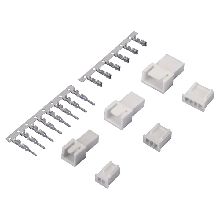
Single-row PA66 male and female housings with 2–12 positions listed; reviewed terminals specify tin-plated phosphor bronze.
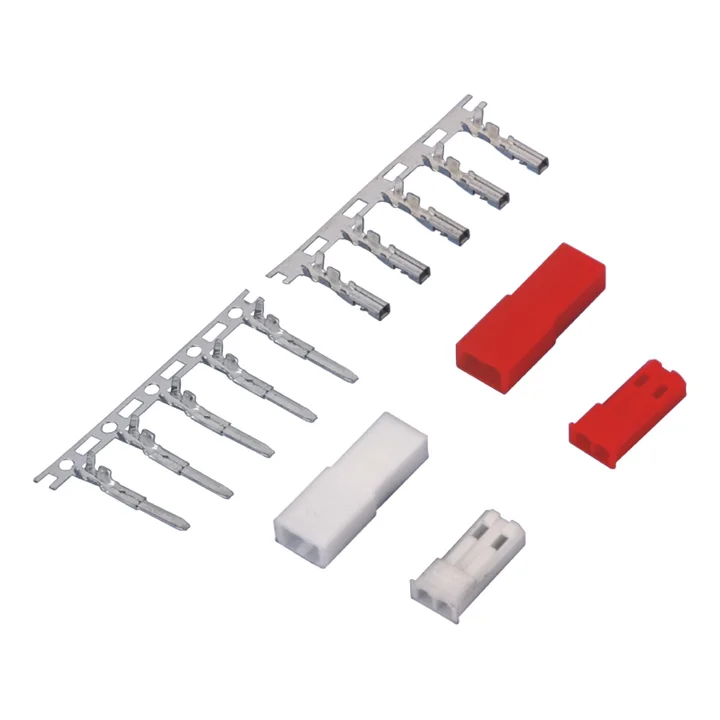
Two-position PA66 male and female housings, shown in white and red.
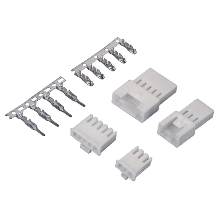
Single-row PA66 male and female housings with 2–12 positions listed; reviewed terminals specify tin-plated phosphor bronze.
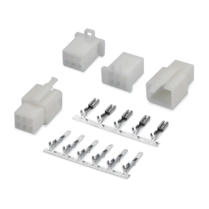
Construction details for this series are awaiting drawing confirmation.
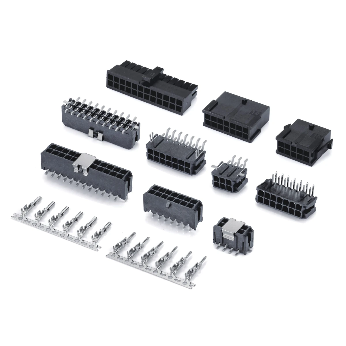
Single- and dual-row cable housings, crimp contacts, and THT or SMT board connectors for wire-to-wire and wire-to-board configurations.
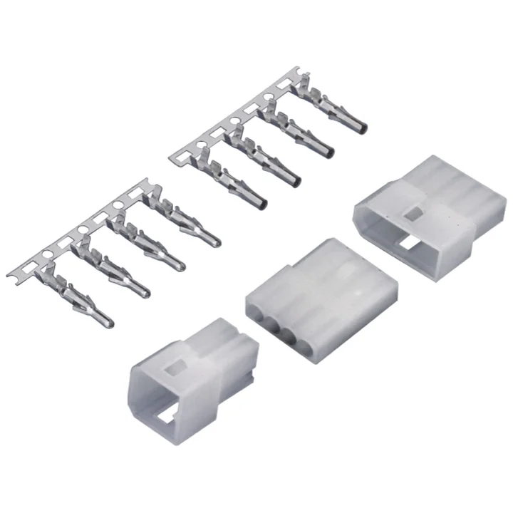
The drawing specifies 3.70 mm pitch for the PA66 male and female housings, with 2–12 positions listed.
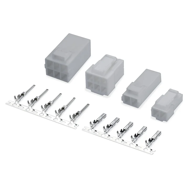
Construction details for this series are awaiting drawing confirmation.
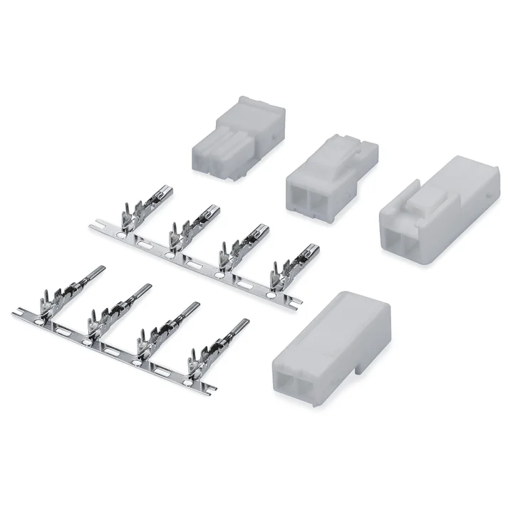
Construction details for this series are awaiting drawing confirmation.
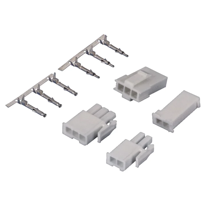
PA66 male and female housings include single- and multiple-row layouts.
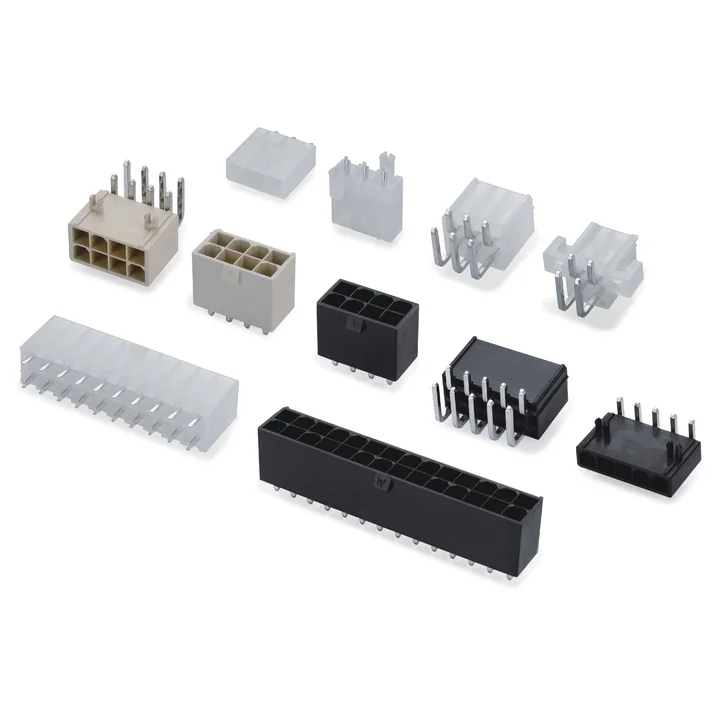
PA66 single- and dual-row male and female housings are documented.
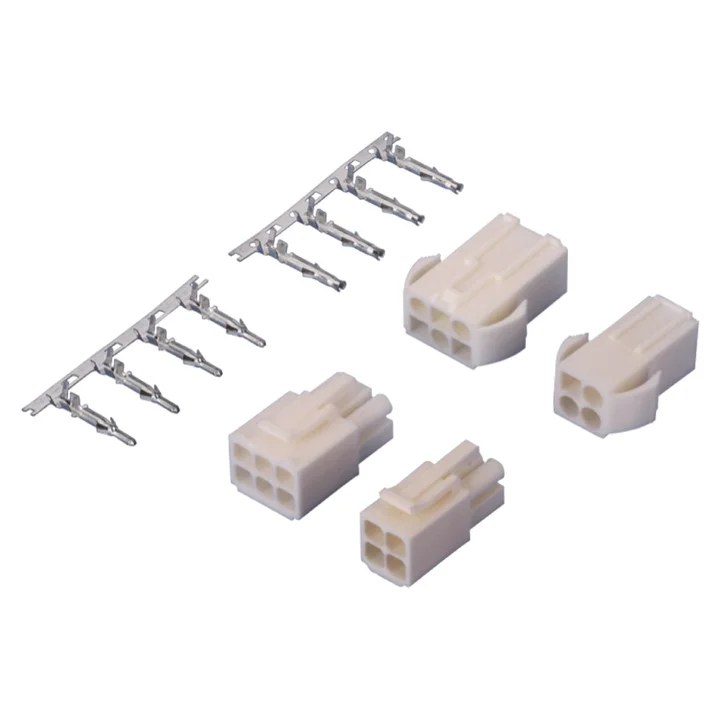
PA66 male and female housings include single-row 2-, 3- and 4-position layouts and 2 × 2, 2 × 3 and 3 × 3 layouts.
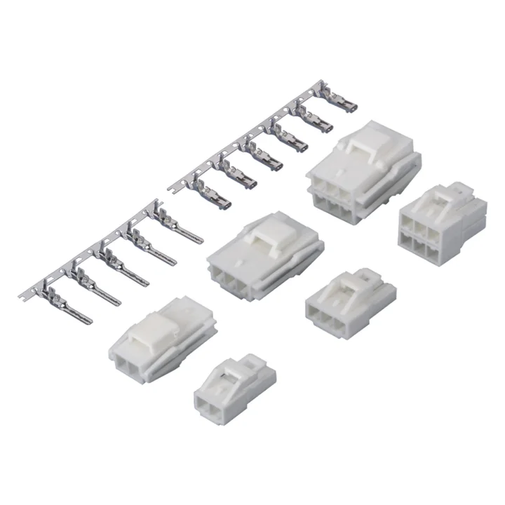
PA66 single-row 2- and 3-position housings and multiple-row layouts are documented.
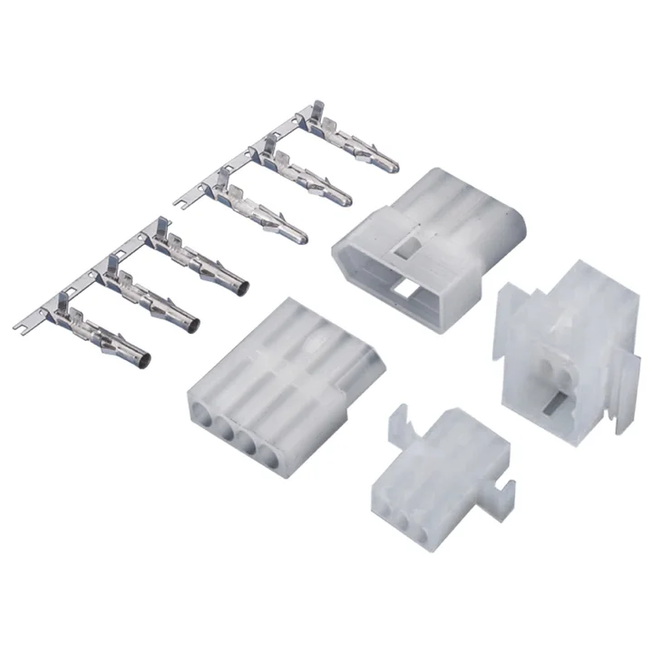
Three-position PA66 male and female housings with tin-plated phosphor-bronze terminals are shown.
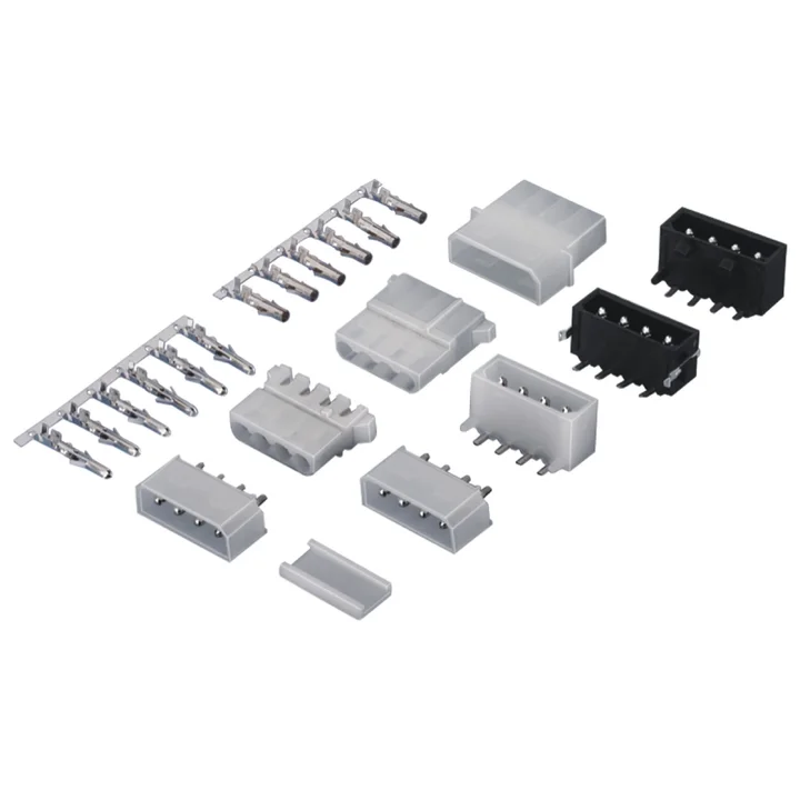
A four-position PA66 female housing and separate right-angle and straight through-hole PCB variants are documented.
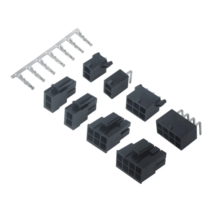
The matched drawings show straight and right-angle through-hole PCB connectors with LCP housings and tin-plated high-conductivity copper-alloy contacts.
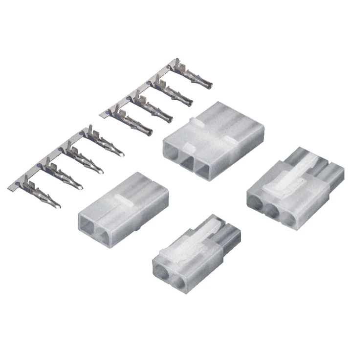
PA66 male and female housings with two- and three-position layouts; a separate male housing includes panel-retention wings.
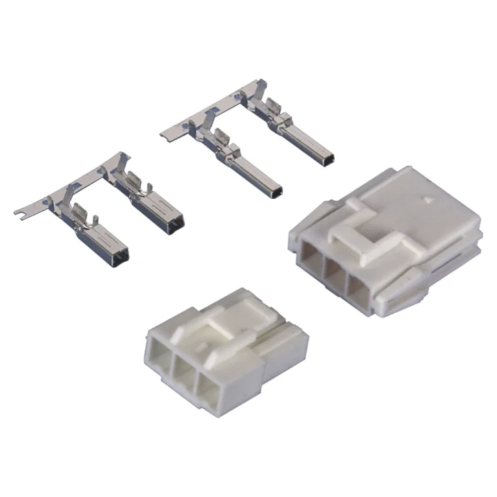
Construction details for this series are awaiting drawing confirmation.
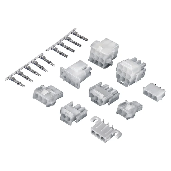
The reviewed single-row housing and PCB drawings specify 6.35 mm pitch.
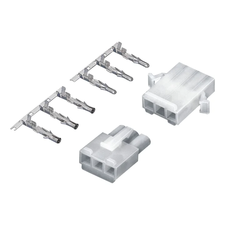
PA66 male and female housing tables list 2, 3, 4, 6, 9, 12 and 15 positions.
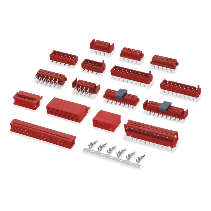
Dual-row PBT cable housings and separate PA9T PCB variants are documented.
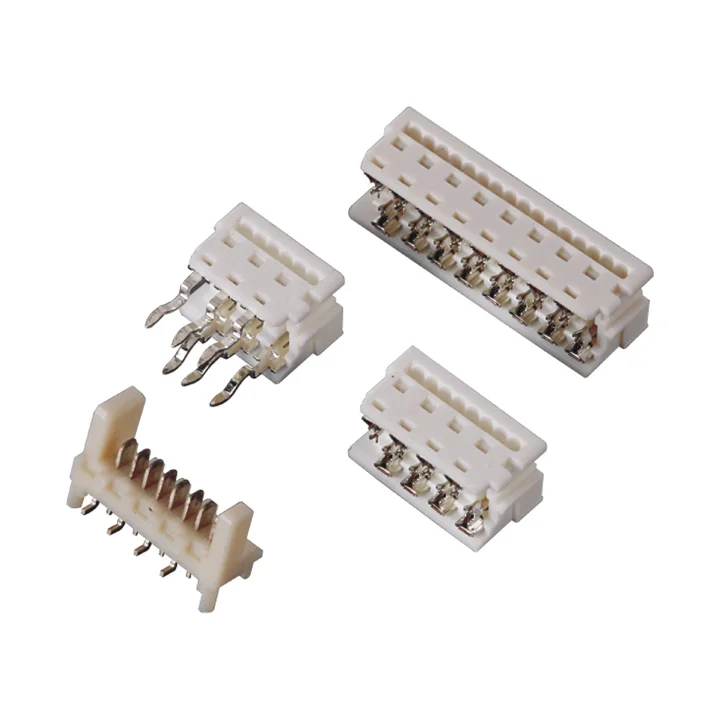
PBT dual-row housings and separate right-angle and straight through-hole constructions are documented.
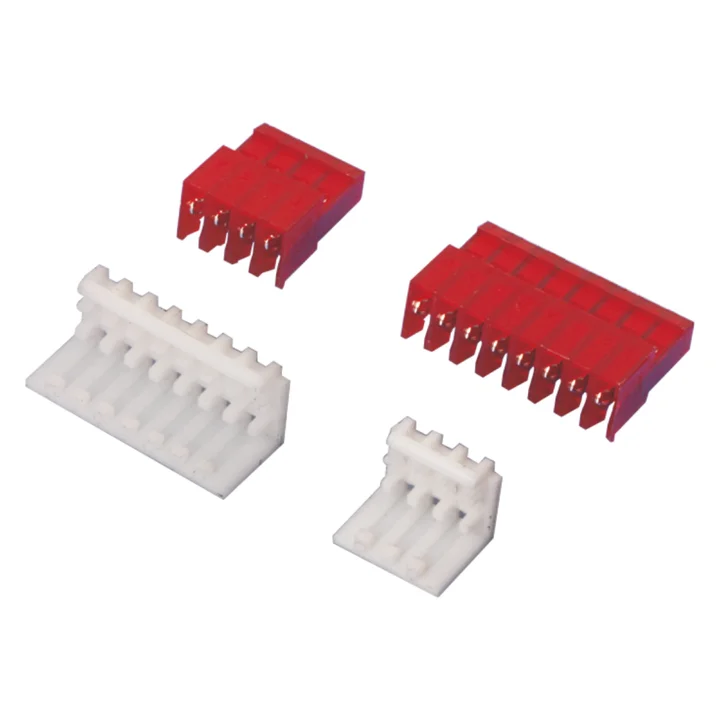
PA66 housings with phosphor-bronze terminals are shown in closed-end and feed-through forms, each with or without polarizing tabs.
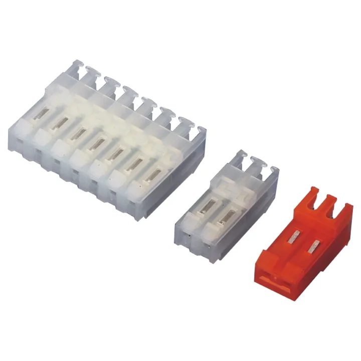
PA66 housings with tin-plated brass contacts and a separate right-angle through-hole PCB construction are documented.
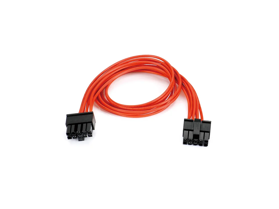
Specify wire lengths, connector ends, pinout and sample or production quantities for a custom discrete-wire assembly.
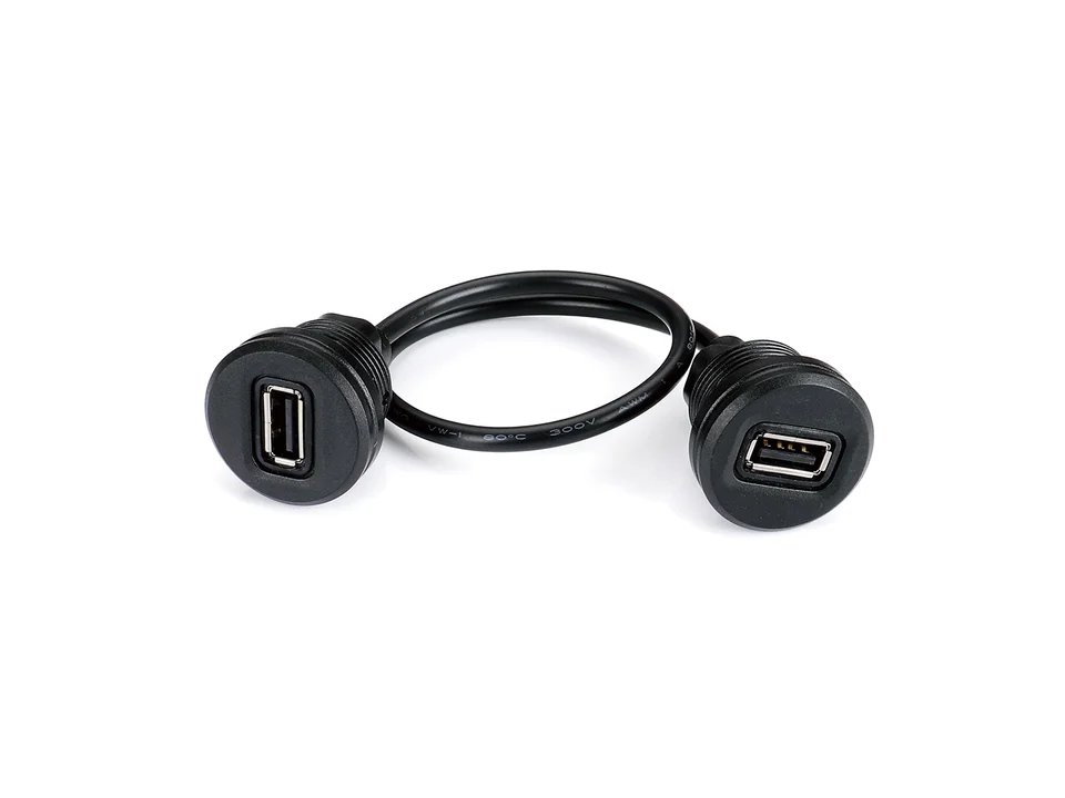
Share the connector ends, cable routing and required molded shape for your custom overmolded cable assembly.
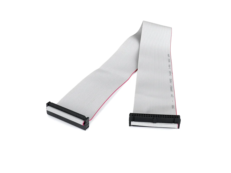
Define cable length, conductor count, pinout and connector orientation for your ribbon or IDC cable assembly.
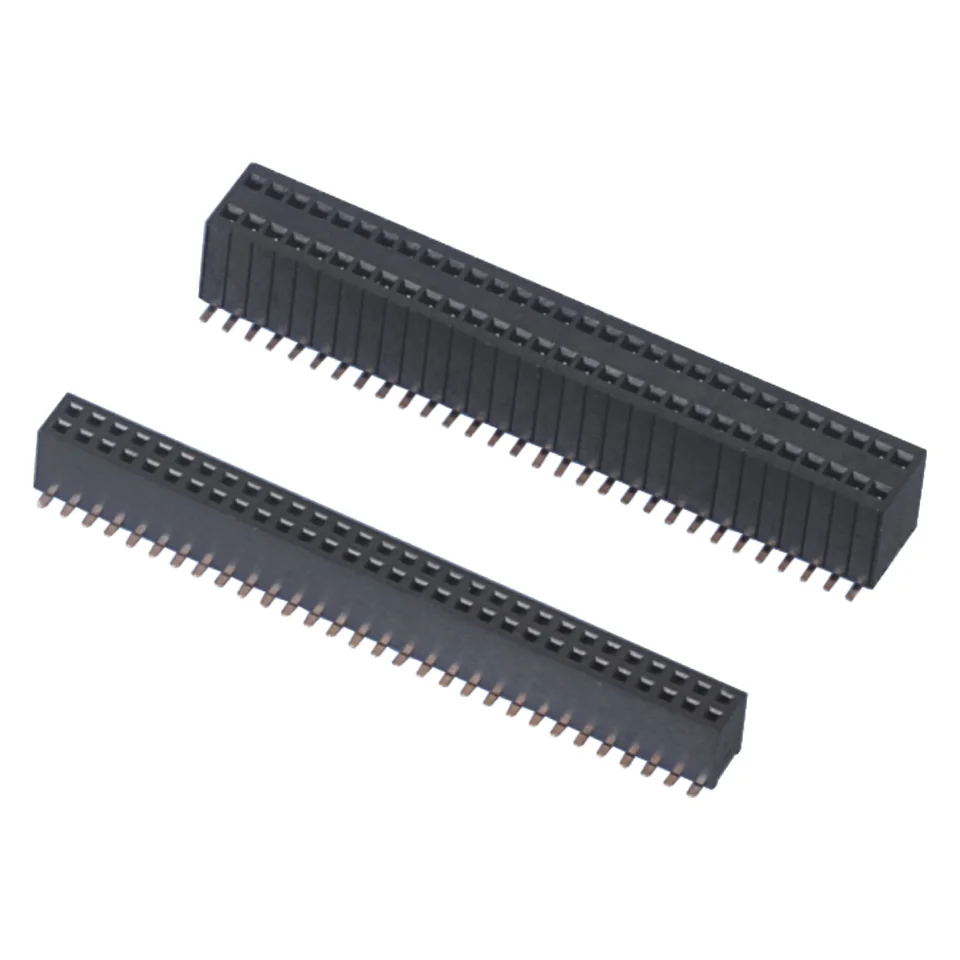
Series photograph. Confirm the selected configuration and dimensions against its drawing.
FH127 1.27 mm female headers with single- and dual-row THT or SMT constructions. Compare socket layout, housing height and the matching PCB footprint.
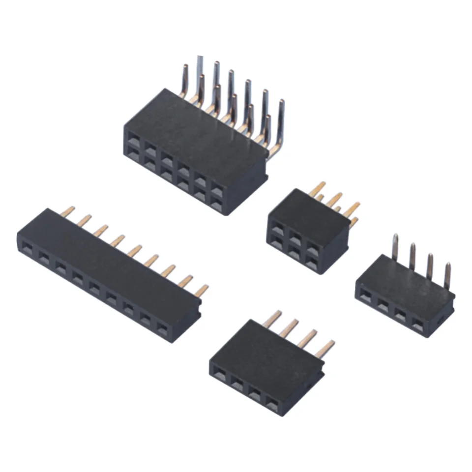
Series photograph. Confirm the selected configuration and dimensions against its drawing.
FH200 2.00 mm female headers with single- or dual-row through-hole and dual-row SMT options. Review socket height, materials and mating dimensions.
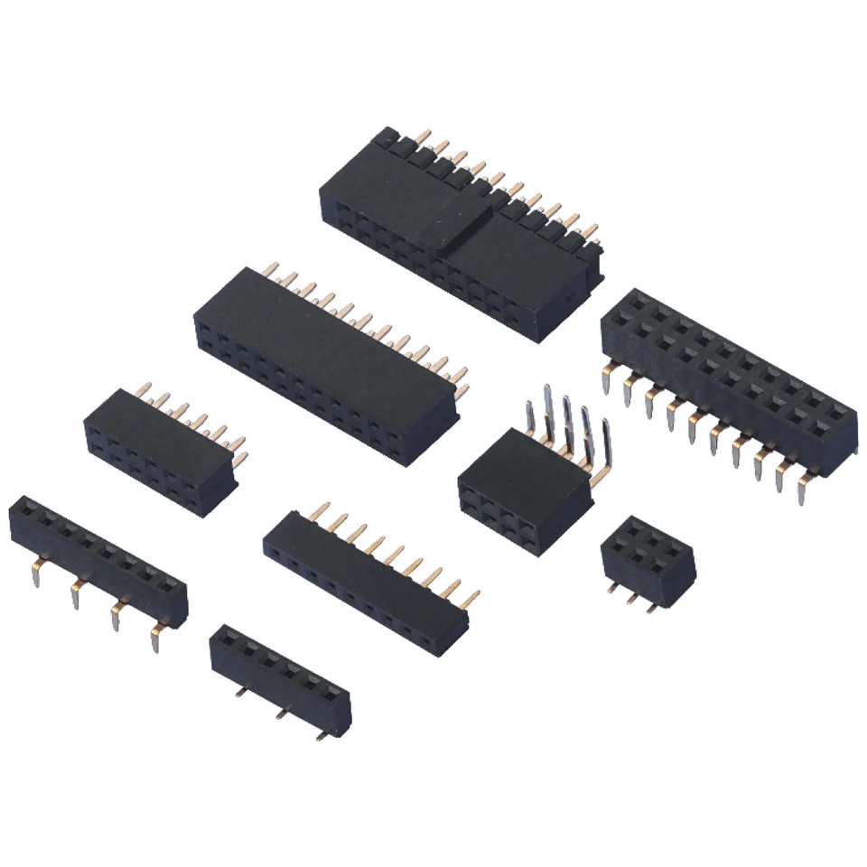
Series photograph. Confirm the selected configuration and dimensions against its drawing.
FH254 2.54 mm female headers in single- and dual-row THT or SMT configurations. Select the socket height, contact construction and PCB footprint.
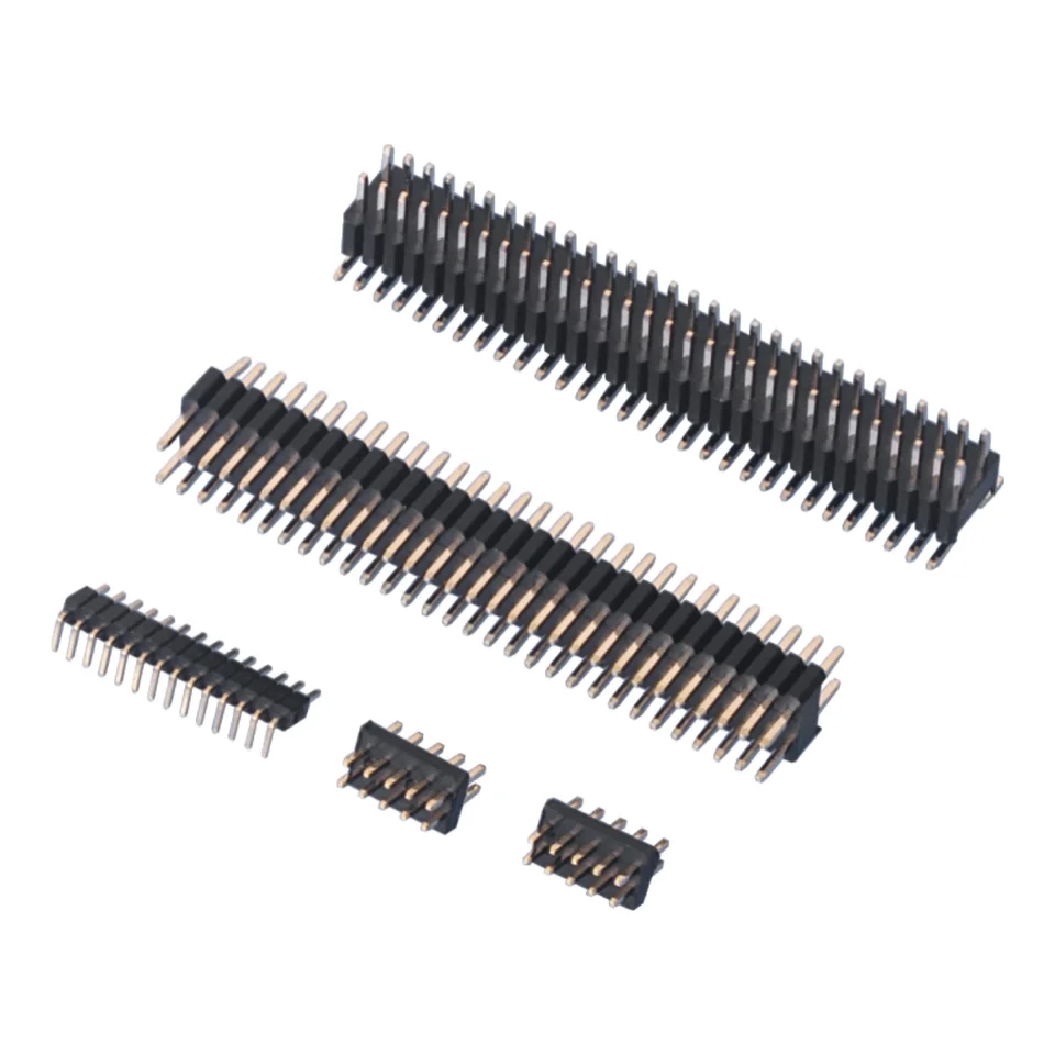
Series photograph. Confirm the selected configuration and dimensions against its drawing.
PH127 1.27 mm pin headers for PCB connections. Compare single- and dual-row THT constructions and dual-row SMT options against your drawing.
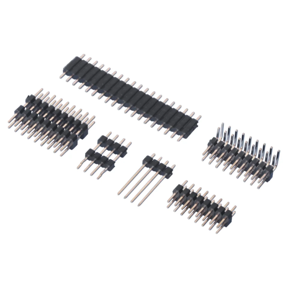
Series photograph. Confirm the selected configuration and dimensions against its drawing.
PH200 2.00 mm pin headers for PCB connections. Compare single- and dual-row THT, dual-row SMT and stacked SMT configurations before selecting dimensions.
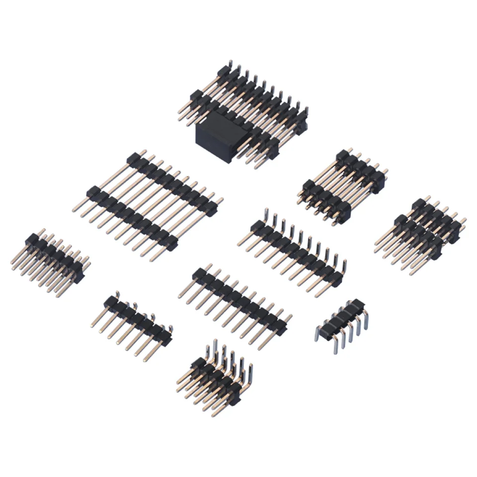
Series photograph. Confirm the selected configuration and dimensions against its drawing.
PH254 2.54 mm pin headers with THT, stacked THT and selected SMT constructions. Review row layout, pin lengths and PCB footprint for the exact variant.
Pin & female headers
Compare six PH and FH series at 1.27 mm, 2.00 mm and 2.54 mm pitch. Choose a starting series, then send your drawing and quantity so we can review the exact configuration.
PH series: exposed-pin connectors. Start with pitch, then specify the row layout, pin length and PCB termination.
These are selection examples, not a complete variant list. Matching pitch alone does not establish mating compatibility.
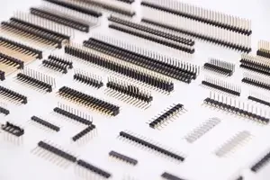
Right-angle dual-row variant shown in the drawing. Select the required pin count, insulator height and pin dimensions.
View PH127 details Drawing (PDF)Right-angle dual-row variant shown in the drawing. Confirm row layout, insulator dimensions and PCB hole pattern.
View PH200 details Drawing (PDF)Right-angle dual-row variant shown in the drawing. Confirm exposed pin length, solder-tail length and mating clearance.
View PH254 details Drawing (PDF)FH series: socket connectors. Start with pitch, then specify the mating pin, socket layout and installed height.
These are selection examples, not a complete variant list. Matching pitch alone does not establish mating compatibility.
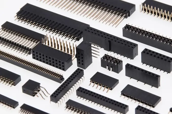
Dual-row socket variant shown in the drawing. Confirm insertion direction, housing height and solder-tail dimensions for the selected configuration.
View FH127 details Drawing (PDF)Right-angle dual-row socket variant shown in the drawing. Confirm housing height, terminal geometry and PCB footprint.
View FH200 details Drawing (PDF)Right-angle dual-row socket variant shown in the drawing. Select the housing dimensions and confirm solder-tail length and mating geometry.
View FH254 details Drawing (PDF)Include the series, pitch, number of rows and positions, mounting method, required dimensions and quantity in your request. Ask for the matching drawing before confirming the order.
Engineering response
Send the released drawing, required circuit count and project quantity for a product-specific review.