
Crimp housing and terminal
The PA66 housing lists 2–15 positions. The tin-plated phosphor-bronze terminal drawing specifies 18–22 AWG wire.
A 3.96 mm single-row wire-to-board connector system with crimp housings and right-angle or vertical through-hole board connectors. The reviewed drawings list 2–15 positions with 18–22 AWG terminals.
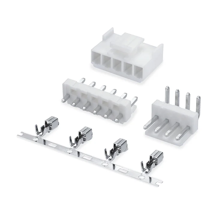
Connector construction
Select the housing, contacts and mating connector together. The available circuit counts and materials depend on the specific drawing, rather than one range covering every variant.
The PA66 housing lists 2–15 positions. The tin-plated phosphor-bronze terminal drawing specifies 18–22 AWG wire.
The right-angle drawing lists 2–15 positions with a PA66 body and tin-plated brass pins. Check side-entry clearance and the PCB hole pattern.
The vertical drawing also lists 2–15 positions with a PA66 body and tin-plated brass pins. Its dimensions differ from the right-angle connector; SMT is not established by these drawings.
Specifications
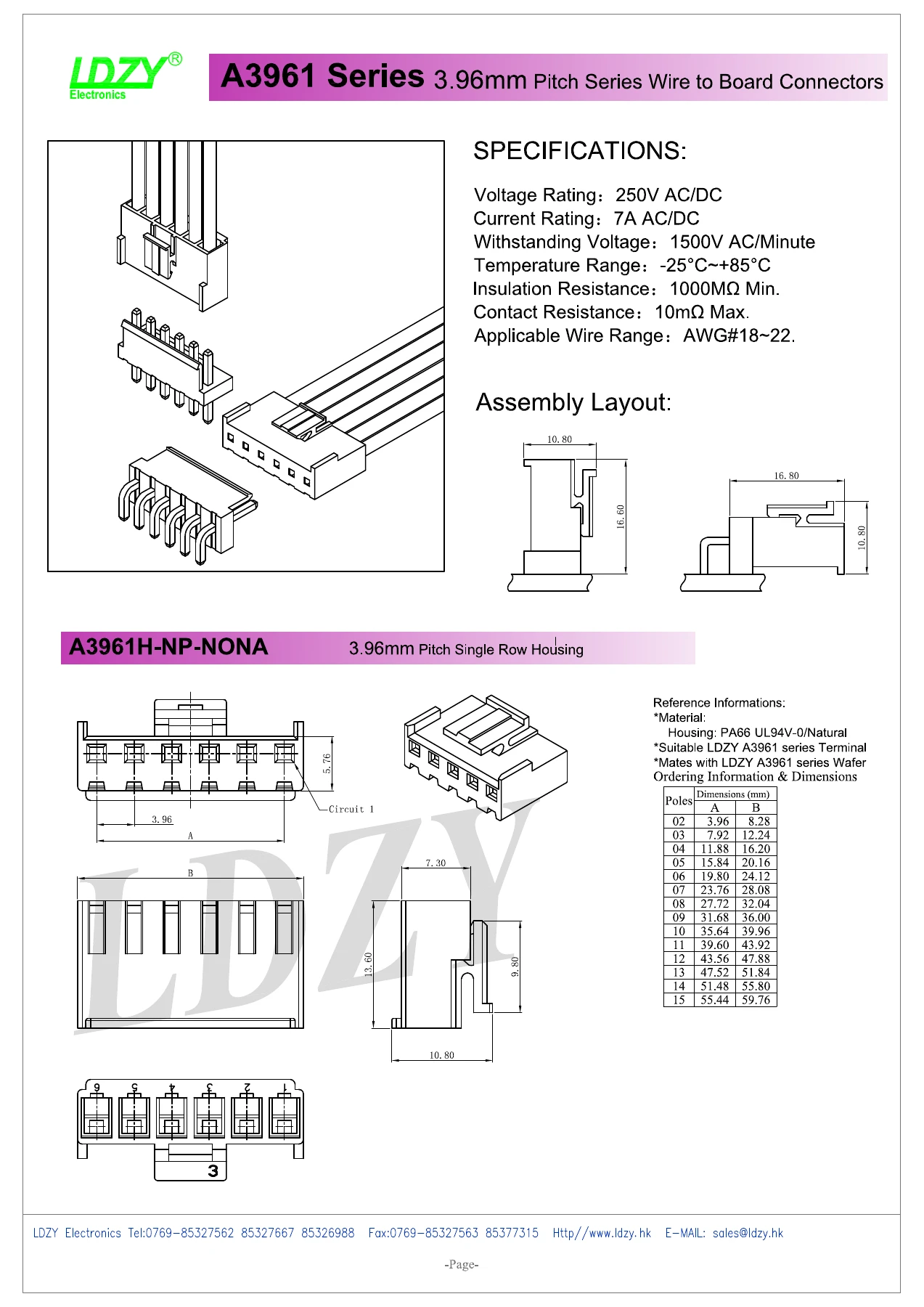
Dimensions, materials and electrical ratings are configuration-specific. Refer to the corresponding technical drawing for part selection.
| Parameter | Specification |
|---|---|
| Pitch | 3.96 mm |
| Configuration | Single-row wire-to-board |
| Listed positions | 2–15 in the housing and THT drawings |
| Current rating | 7 A AC/DC |
| Voltage rating | 250 V AC/DC |
| Applicable wire range | 18–22 AWG |
| PCB termination | THT |
| Orientation | right-angle / vertical |
Drawings
View the drawings below or open the original PDF. Dimensions and specifications apply to the configuration and revision shown.
Engineering response
Send the released drawing, target configuration, quantities and any required documentation so the technical team can confirm the next step.