
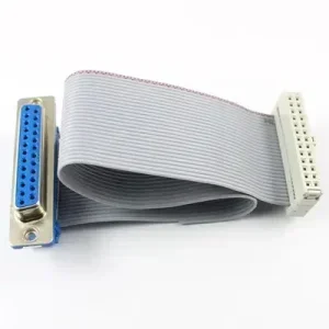
D-sub to IDC socket
Define each interface, connector gender, mounting requirements and the complete pin-to-pin map.
Custom cable assemblies
Flat ribbon cable assemblies built to your drawing, sample or project requirements. Customize IDC, D-sub and crimp-contact terminations, cable layout and pin mapping as one complete assembly.
Request a Quote100% electrical testing · Samples generally free · Typical production MOQ: 500 assemblies
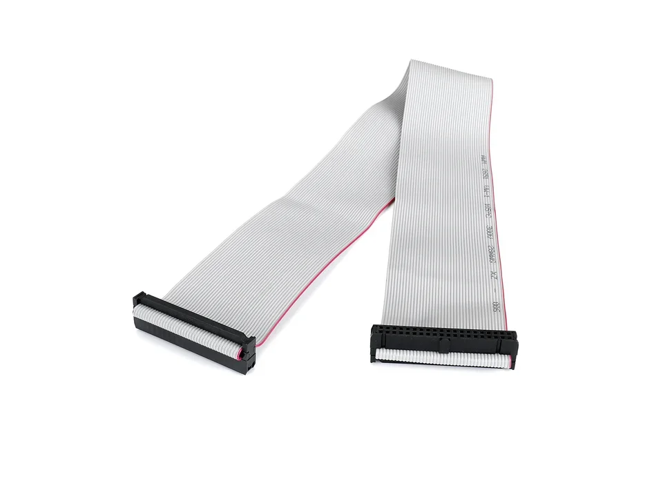
Start with a finished assembly similar to your requirements. These photographs show construction examples; mating compatibility and electrical mapping require project confirmation.
Define each interface, connector gender, mounting requirements and the complete pin-to-pin map.
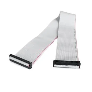
Confirm the mating headers, keying, pin-one reference and cable exit direction at both ends.
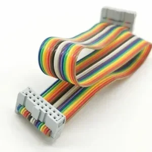
Specify conductor count, color sequence and connector orientation. Color alone does not define the electrical mapping.
We support the termination and layout options above without a fixed catalogue range for pitch, wire gauge or conductor count. The cable, connectors and construction are selected and confirmed against your project requirements.
| Item | What to specify |
|---|---|
| Termination | IDC sockets, D-sub connectors or crimp-contact housings; define each end separately. |
| Cable construction | Gray flat ribbon, rainbow ribbon and round-to-flat layouts; specify conductor construction and insulation requirements. |
| Layout | Two-ended, single-ended, multi-connector daisy-chain, split or breakout sections and planned folds. |
| Pitch and conductor count | Specify connector pitch and ribbon conductor spacing separately, with position and conductor counts. |
| Wire gauge and materials | Provide the cable specification or operating requirements. Gauge, insulation and component fit are reviewed together. |
| Length and routing | Give finished length, measurement reference points, tolerances, connector positions and installation clearances. |
| Electrical mapping | Provide an end-to-end connection table, pin-one reference and the viewing direction used for each connector. |
| Identification and protection | Discuss labels, color sequence, keying, strain relief and packaging requirements. |
Mechanical orientation and electrical mapping are separate decisions. A connector facing the opposite direction does not, by itself, define a reversed pinout.
State whether your drawing shows the mating face or wire-entry side. Mark the key, latch and pin-one position at each end.
Show how the edge stripe or selected conductor connects to pin one. Confirm the convention on the drawing and sample.
Use a connection table rather than relying on “same direction” or “reversed.”
| End A pin | End B pin |
|---|---|
| 1 | 1 |
| 2 | 2 |
| 3 | 3 |
Your approved pin map defines the actual build.
Mark the endpoints used for length measurement, plus connector spacing and folds. Include a routing sketch where installation space matters.
A clear drawing and an approved sample establish the assembly to be produced.
Send your drawing, sample reference or project requirements, including sample and production quantities. We review the construction and quote the project.
With a drawing, we sample to that drawing. With a physical sample, we prepare a drawing before sampling. If no drawing is available, we can assist with one.
Review the sample for mating fit, connector orientation, pin mapping, length and installation. Confirm the final construction before ordering production.
We produce to the confirmed assembly requirements and carry out electrical testing and periodic production inspections.
Production-floor photographs show our wire-processing area and terminal-crimping workstations. They illustrate the workshop rather than a specific ribbon or IDC assembly operation.


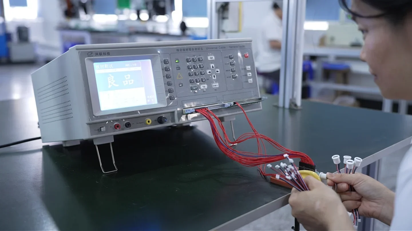
100% electrical testing checks continuity, short circuits and miswiring against the confirmed connection requirements.
Appearance and terminal retention are checked through periodic inspections. Include any additional acceptance criteria or test-document requirements in your inquiry for review.
A drawing, BOM, physical sample reference or marked sketch can start the review. Identify any undecided details.
Drawing and sample review
Give each connector a unique reference and show its position along the ribbon. Record the mating-face view, pin-one reference and cable exit direction at each position. Specify distances between defined measurement points and provide a connection table covering every connector.
Where the ribbon must fold or pass through a confined space, include a routing sketch. During sample review, check connector access, planned folds and installation clearance. Show where the cable is held or guided and identify any movement so these requirements can be reviewed with the construction.
No. IDC is a termination method. A ribbon assembly can use IDC, D-sub or crimp-contact terminations, depending on its selected components and construction.
Yes. We can support multiple connectors, split or breakout sections, folds and round-to-flat layouts. Provide the required positions, connection map and routing details.
They describe different measurements. Define both, or provide the selected component and cable details so their fit can be reviewed.
Yes. We prepare a drawing from the sample before sampling. If you already have a drawing, we sample to it; if you have neither, we can assist with drawing preparation.
Samples are generally free. We do not charge crimp-tooling or fixture fees.
The typical minimum production order is 500 assemblies. Include the required quantity in your inquiry.
Every completed assembly is electrically tested for continuity, short circuits and miswiring. Appearance and terminal retention are checked through periodic production inspections.
Appearance alone does not establish compatibility. Confirm the mating interface, pitch, position count, keying, electrical mapping and required operating conditions before sample approval.
Share your drawing, sample requirements or project description.