
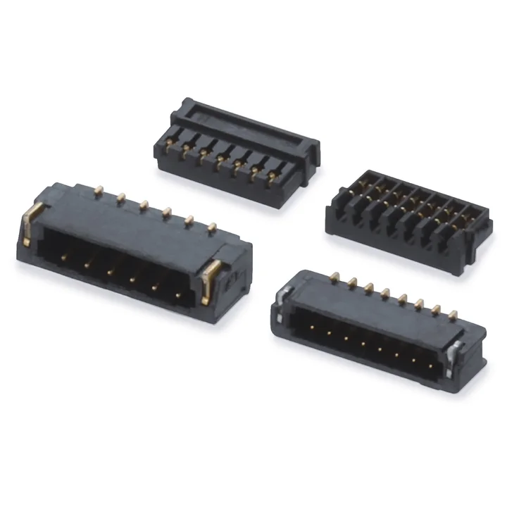
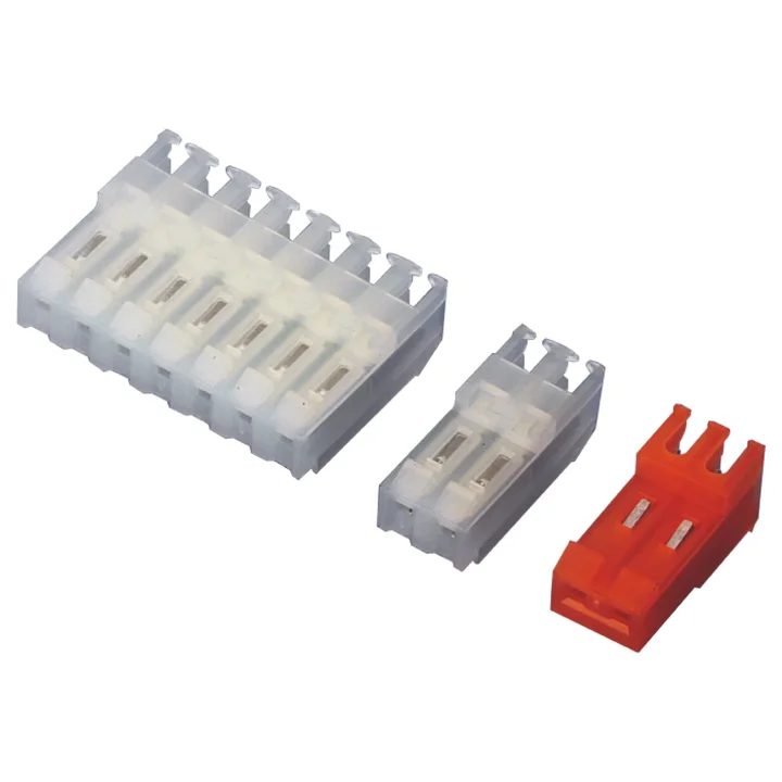
A0600 connector series
The housing table lists 2–16 positions; the drawing specifies LCP and gold-plated phosphor-bronze terminals.
Single-row housingSMT board connector
Connector selection
Compare connector series for connecting wires to a PCB. Select the housing, contact and board connector configuration for your application.
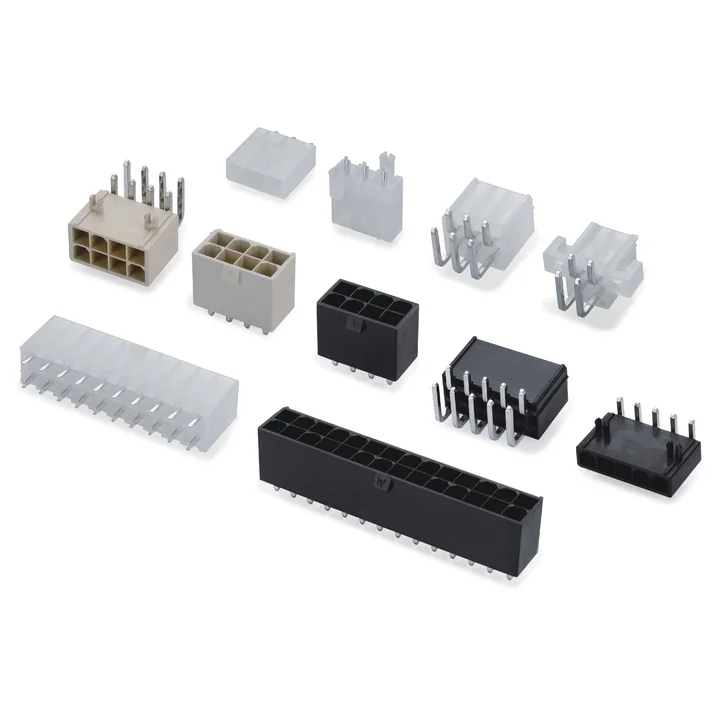
Use the filters to compare available series. A series can appear in more than one connection category; its details and quotation request remain on the same product page. Matching pitch alone does not establish compatibility.
69 products shown
The housing table lists 2–16 positions; the drawing specifies LCP and gold-plated phosphor-bronze terminals.
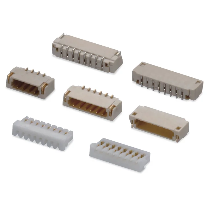
The A0800 housing drawing specifies PA66.
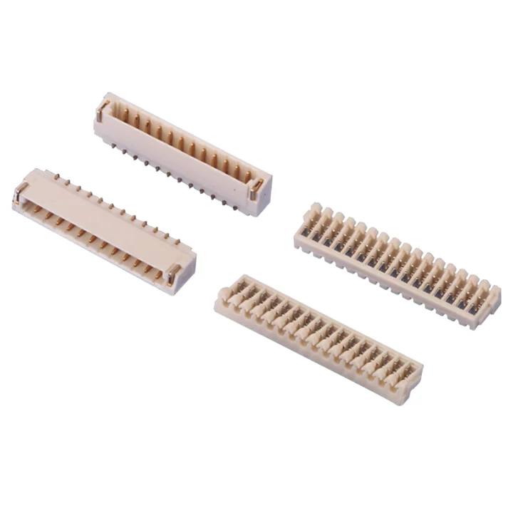
Both single-row housing tables list 2–20 positions and LCP bodies, with gold-plated or tin-plated phosphor-bronze terminals as specified for the selected configuration.
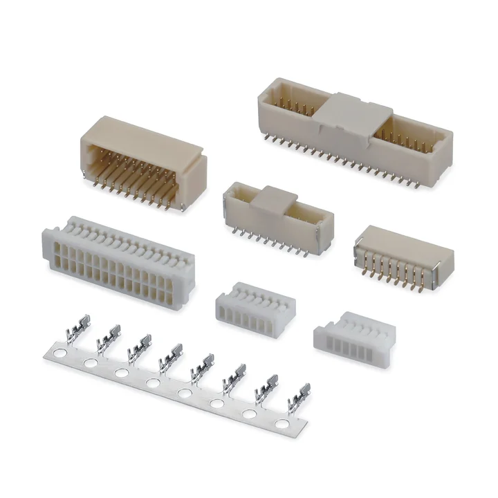
Wire-to-board connector system with crimp housings and SMT board connectors.
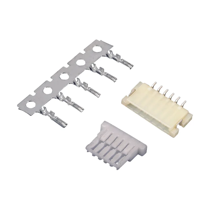
The drawing specifies a white Nylon 66 housing and a tin-plated phosphor-bronze crimp terminal.
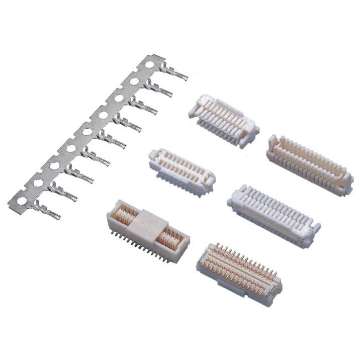
The housing table lists 20, 30, 40 and 50 total positions, with Nylon 66 bodies and two profiles shown.
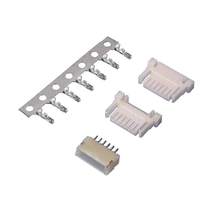
The housing table lists 2–20 positions with a white Nylon 66 body and a tin-plated phosphor-bronze terminal.
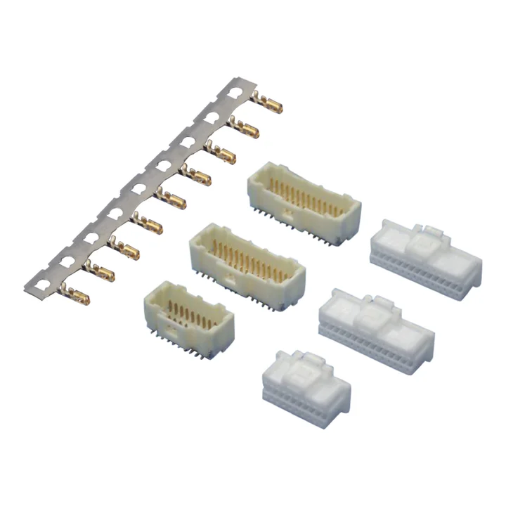
The housing table lists 2 × 2 through 2 × 20 positions and specifies Nylon 66.
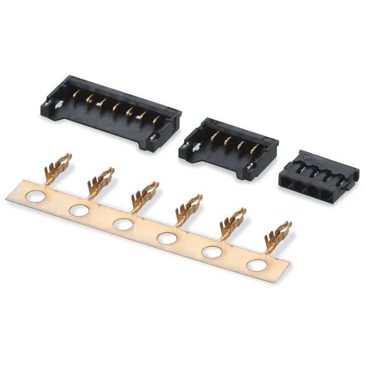
The housing table lists 2–15 positions and a black PA10T body.
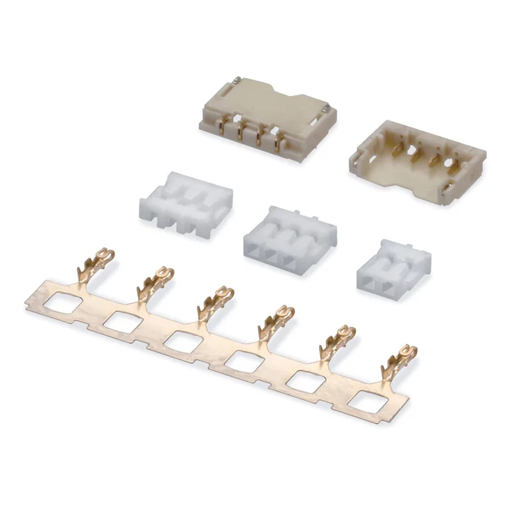
The housing table lists 1–15 positions and specifies PA66 in white or black.
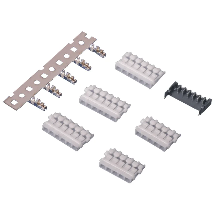
The housing table lists 2–6 positions and a white PBT body, with two housing profiles shown.
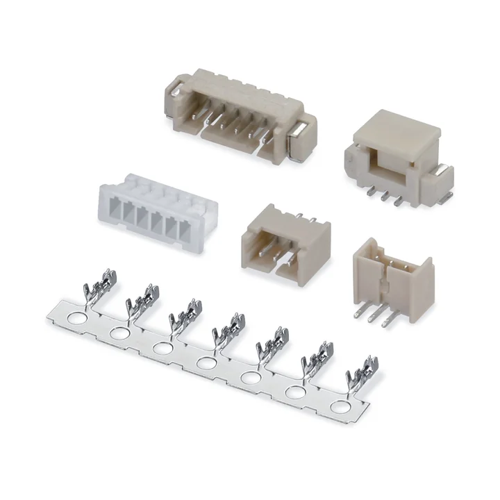
The female housing table lists 2–18 positions; the male housing table lists 2–15.
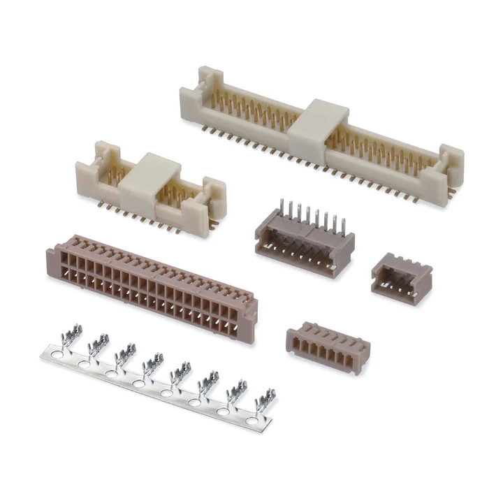
The single-row PA66 housing table lists 2–15 positions.
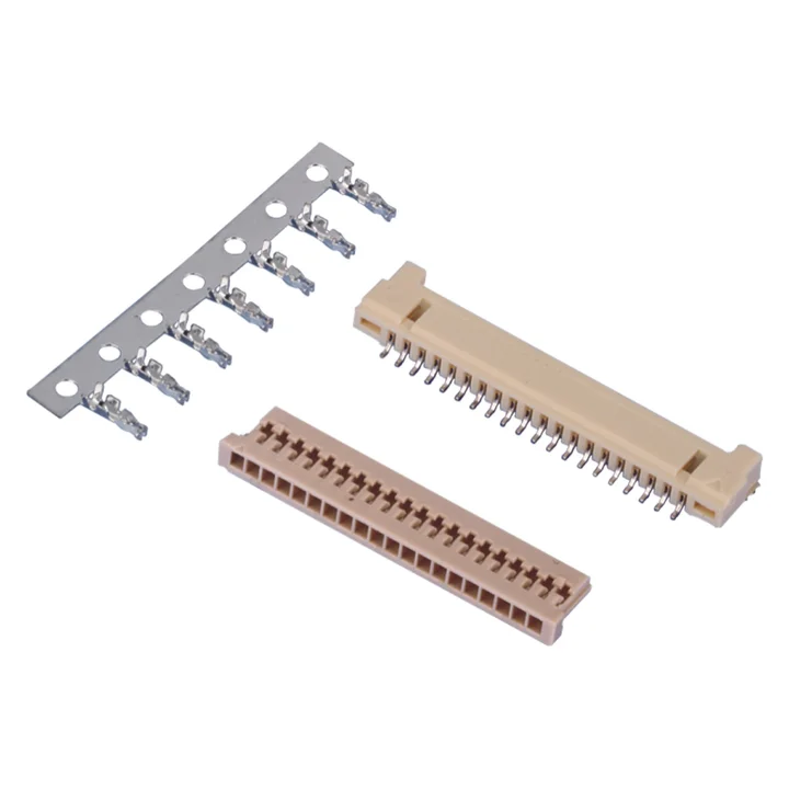
The two housing profiles specify PA66.
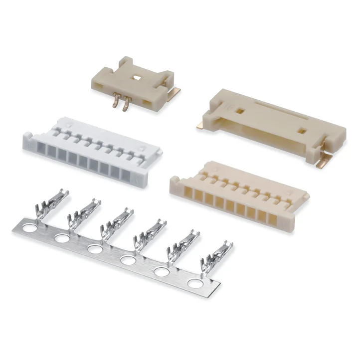
Two PA66 housing profiles are shown with different position tables and dimensions.
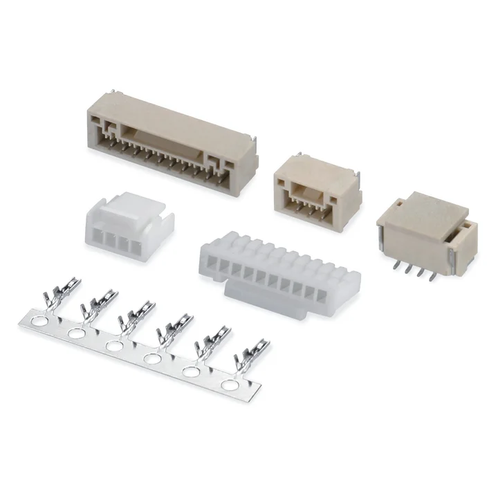
Single-row wire-to-board connector system with crimp housings and right-angle or vertical SMT board connectors.
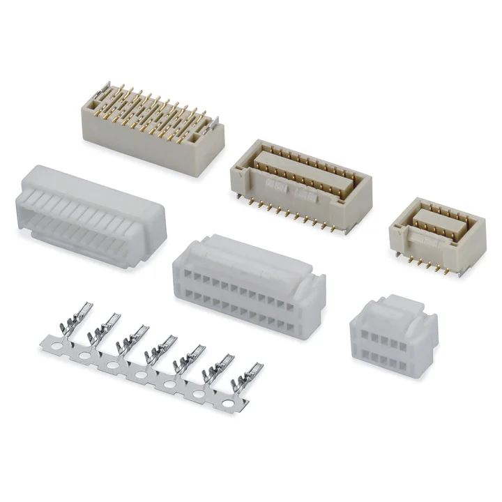
The PA66 housing table lists 2 × 5 through 2 × 16, then 2 × 18, 2 × 19 and 2 × 20.
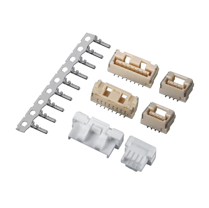
The PA66 housing table lists 2–15 positions, with different body features for smaller and larger configurations.
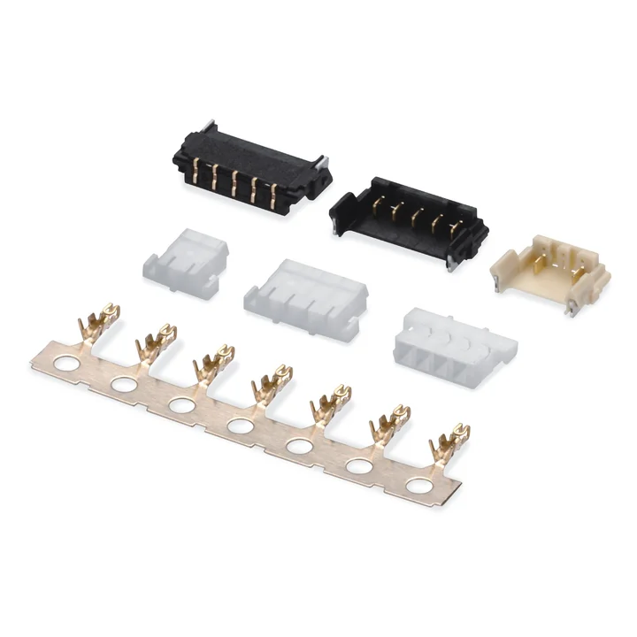
The PA66 housing table lists 2–12 positions in natural or black, with a distinct two-position profile.
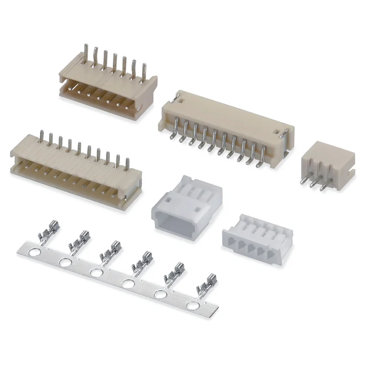
Single-row wire-to-board connector system with crimp housings and through-hole or SMT board connectors.
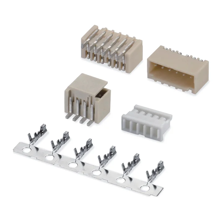
The housing table lists 2–15 positions and specifies PA66 or PBT body options.
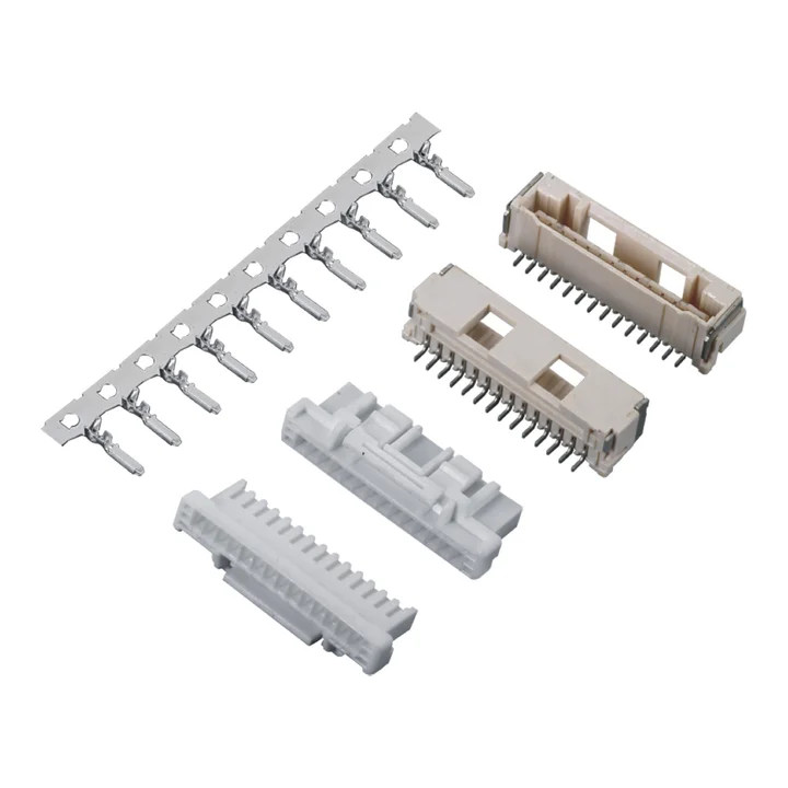
The PBT housing table lists 2–15 positions and shows size-specific latch and body profiles.
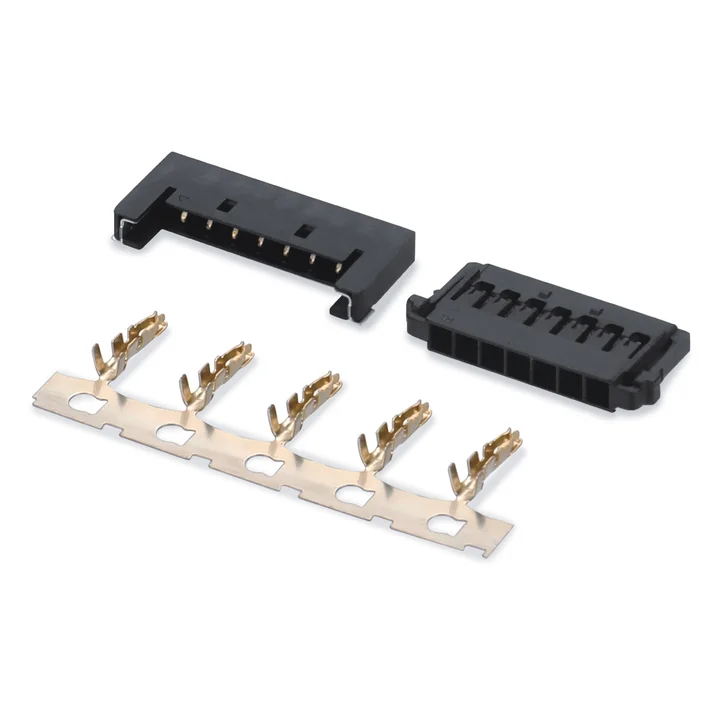
The housing table lists 4, 6, 8, 10 and 12 positions and a black PA66 body.
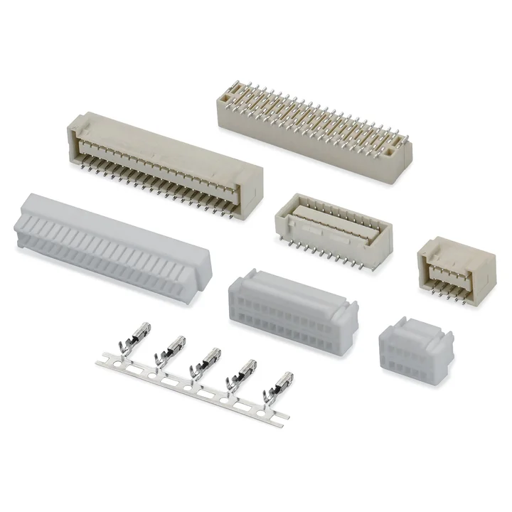
The PA66 housing table lists 2 × 5 through 2 × 20 positions with a tin-plated phosphor-bronze crimp terminal.
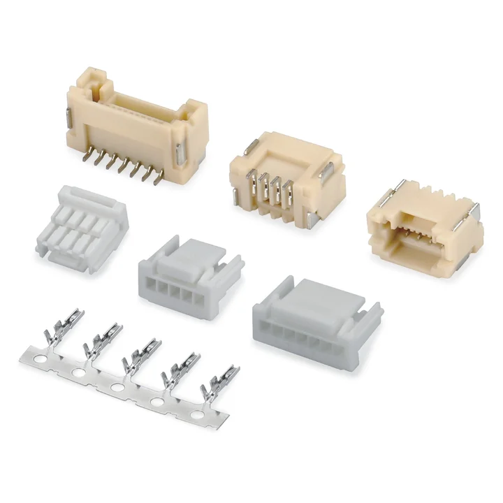
The PBT housing table lists 2–16 positions and size-specific body profiles.
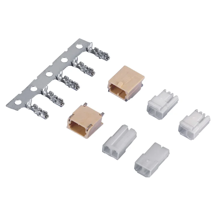
Both reviewed housing drawings are two-position single-row constructions with Nylon 66 bodies; the side and latch features differ.
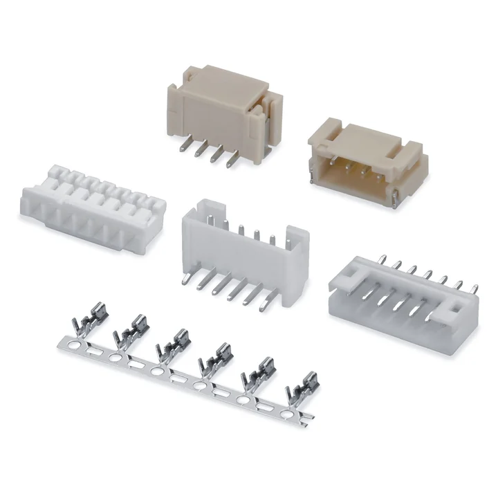
Single-row wire-to-board connector system with crimp housings and THT or SMT board connectors.
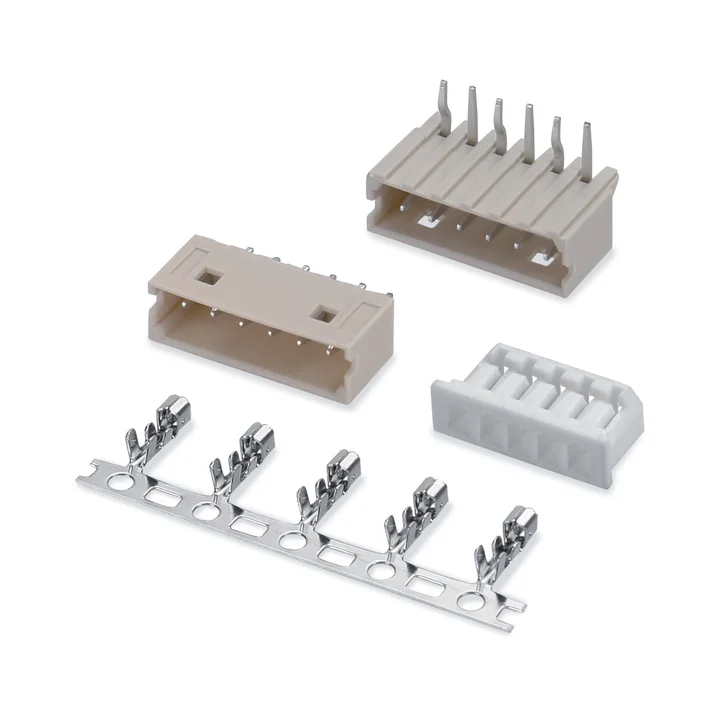
PA66 housing, tin-plated phosphor-bronze crimp terminal and straight or right-angle through-hole board connectors.
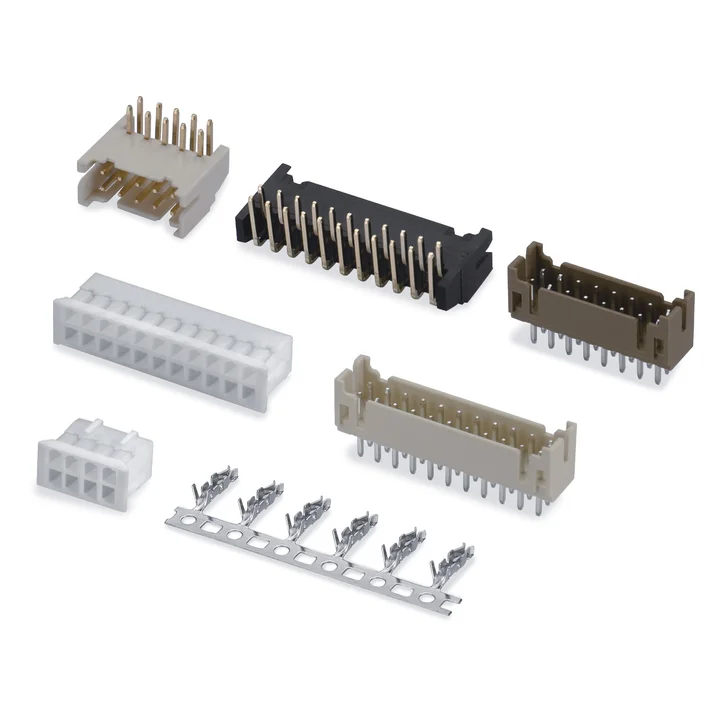
Three housing profiles and straight or right-angle through-hole board connectors are shown.
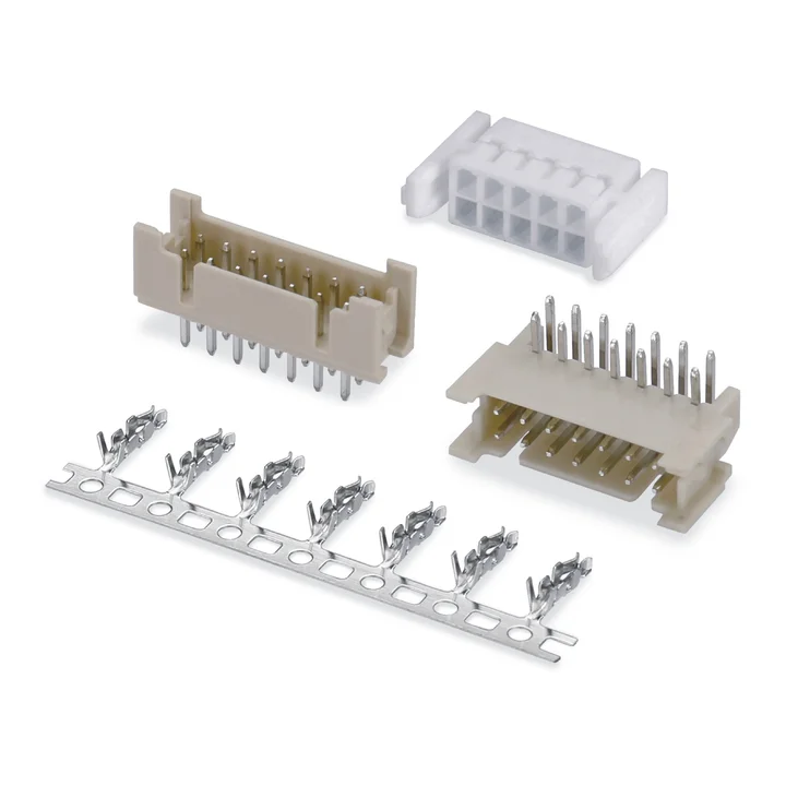
The side-latch housing drawing is paired with a tin-plated phosphor-bronze terminal and straight or right-angle through-hole board connectors.
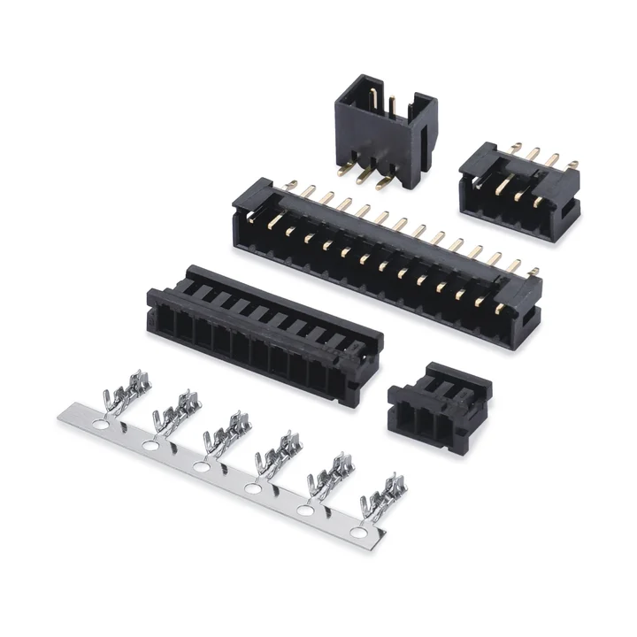
A black PA66 housing and tin-plated phosphor-bronze terminal pair with PA6T through-hole board connectors.
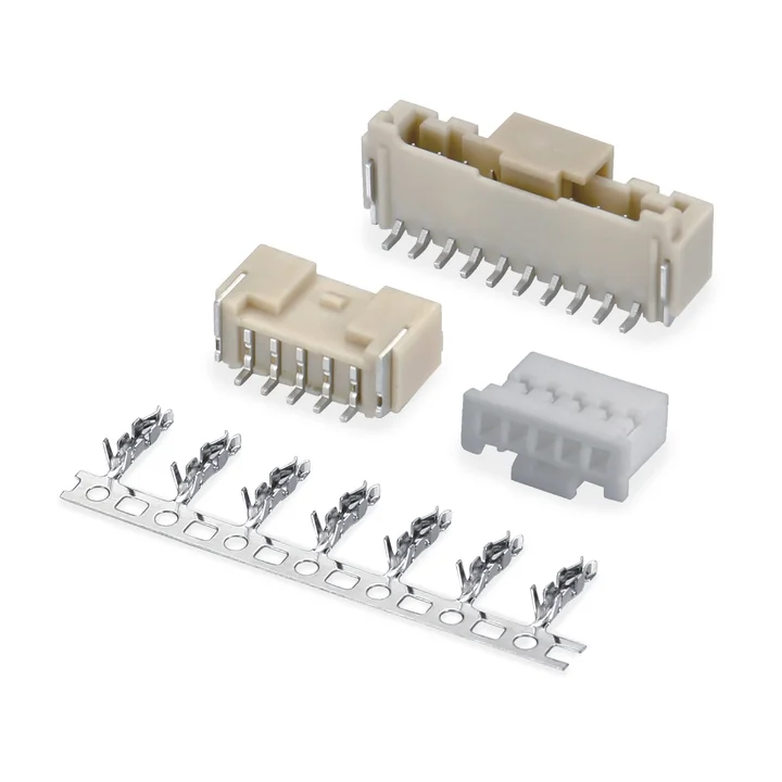
The single-row PA66 housing is shown with PA9T board connectors in straight and right-angle through-hole versions, plus SMT versions with solder tabs.
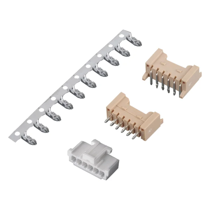
PA66 housing, a tin-plated phosphor-bronze terminal and two through-hole board profiles are documented.
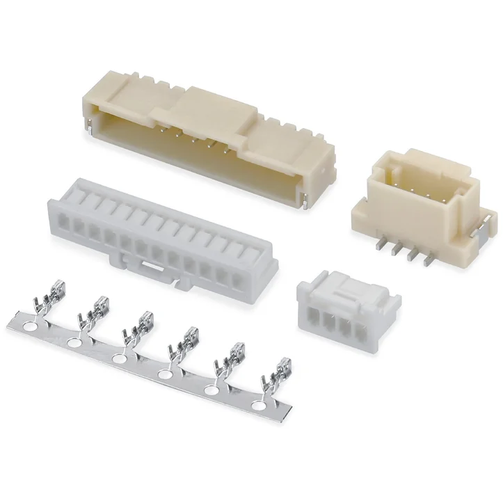
The housing drawing lists PA66 or PBT, while the two SMT board profiles use PA9T.
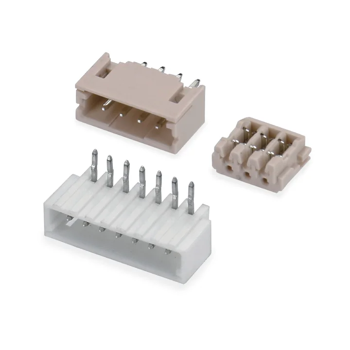
The housing and straight through-hole board variant use glass-filled PA66; the right-angle board variant uses glass-filled PBT.
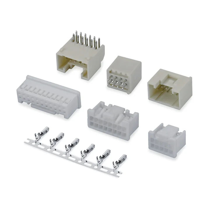
Construction details for this series are awaiting drawing confirmation.
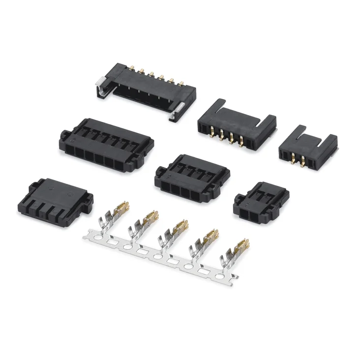
Construction details for this series are awaiting drawing confirmation.
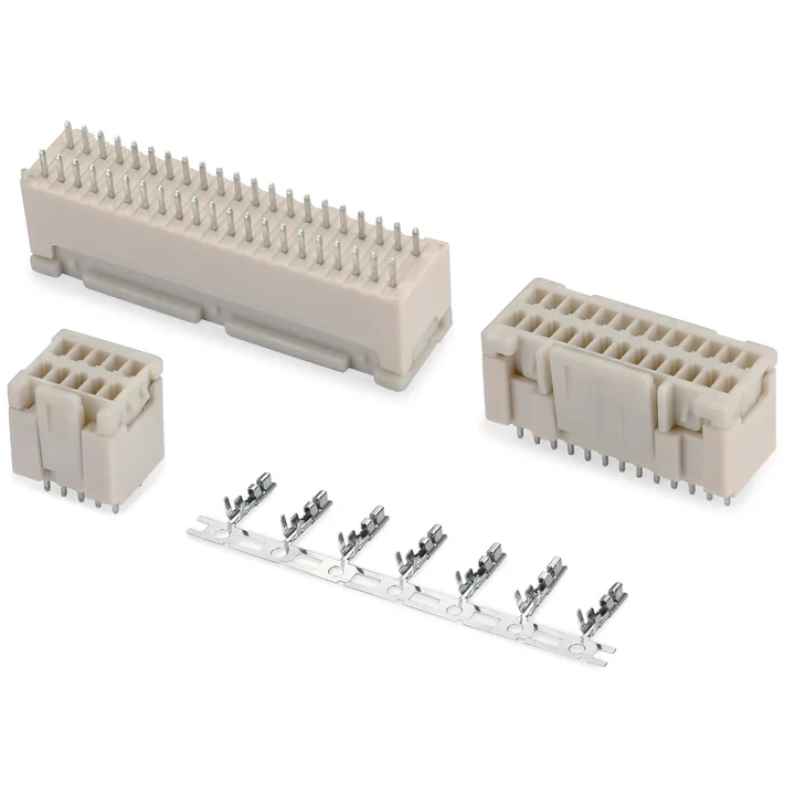
Construction details for this series are awaiting drawing confirmation.
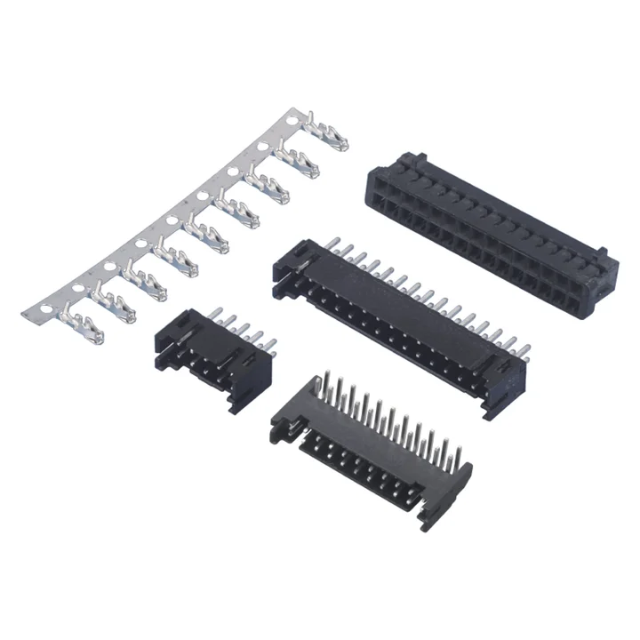
Black PA66 housing and straight or right-angle through-hole board connectors are shown, together with a separate PA6T SMT board profile.
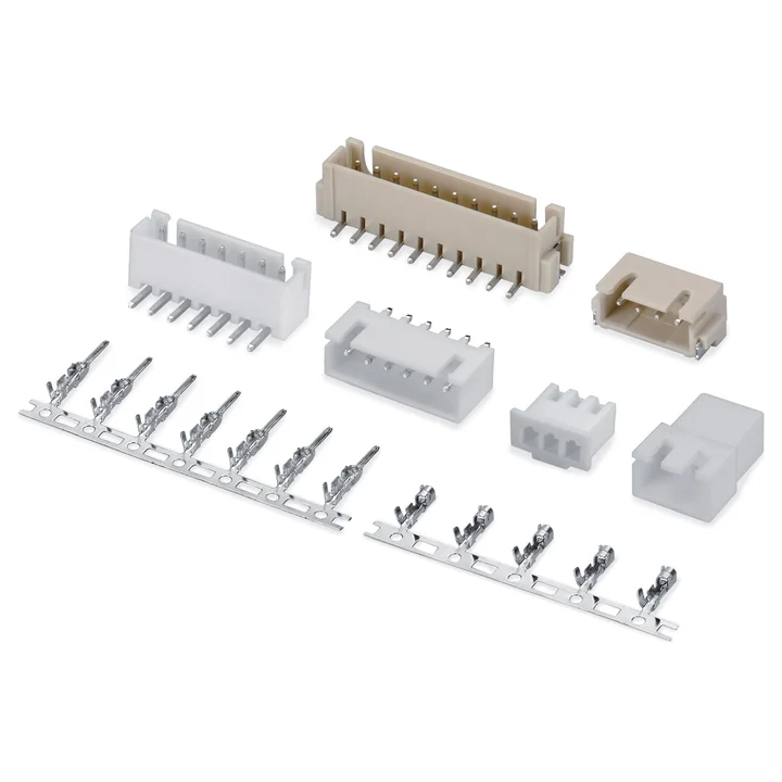
Single-row connector system with crimp housings, male and female terminals, and THT or right-angle SMT board connectors.
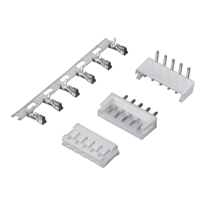
White PA66 housing and straight or right-angle PA66 through-hole board connectors are documented.
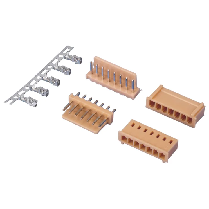
Natural PA66 housing and straight or right-angle PA66 through-hole board connectors are shown with a tin-plated phosphor-bronze crimp terminal.
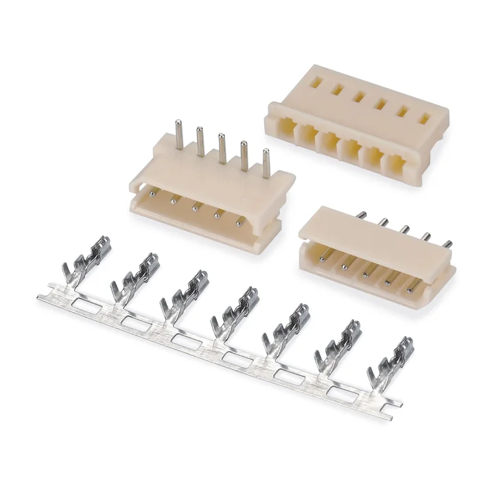
Natural PA66 housing and straight or right-angle PA66 through-hole board connectors are shown with a tin-plated phosphor-bronze terminal.
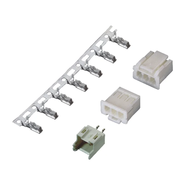
A white PA66 housing is documented with a crimp terminal and a natural PA66 straight through-hole board connector; the terminal and board pins are tin-plated phosphor bronze.
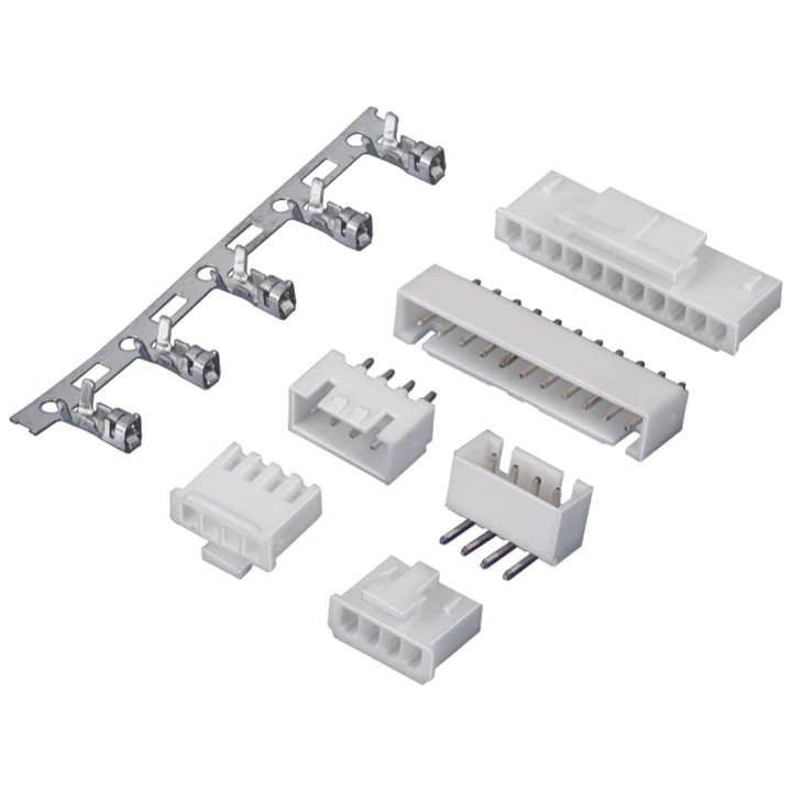
The reviewed white PA66 housing is the B profile.
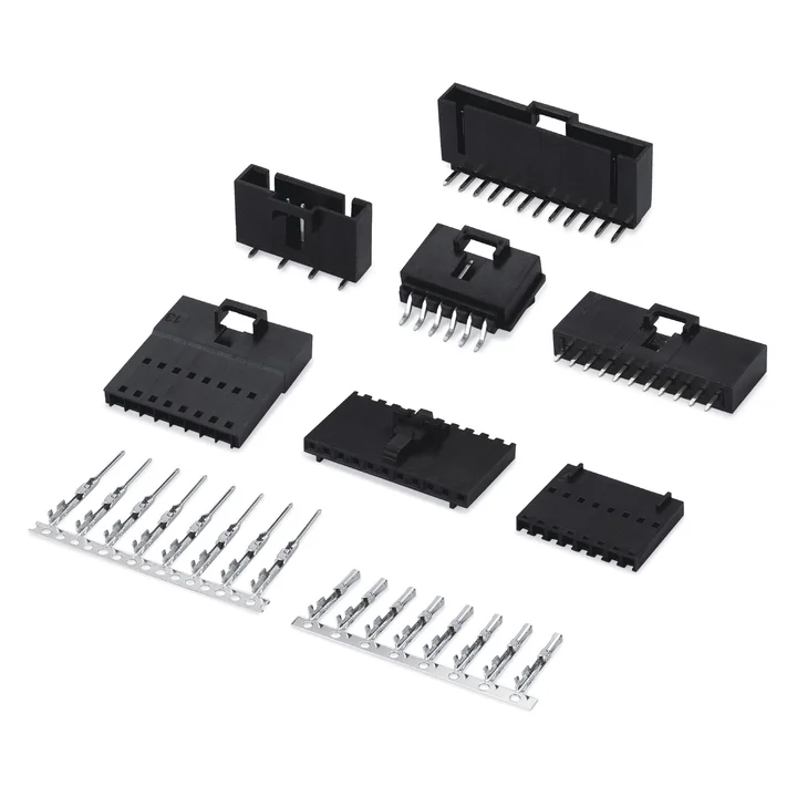
Separate male and female PA66 housing profiles are documented, with straight and right-angle through-hole and SMT board variants.
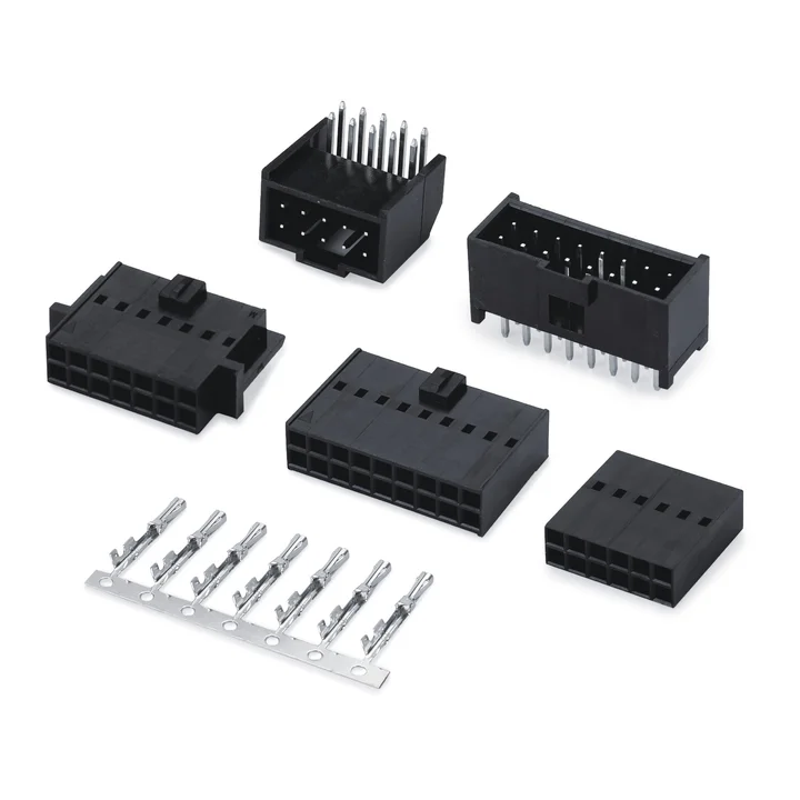
The HA housing is explicitly identified as a black PBT dual-row profile.
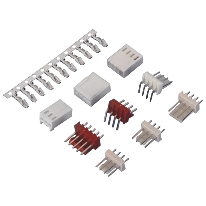
Two PA66 housing profiles and several straight or right-angle PA66 through-hole board connector profiles are documented.
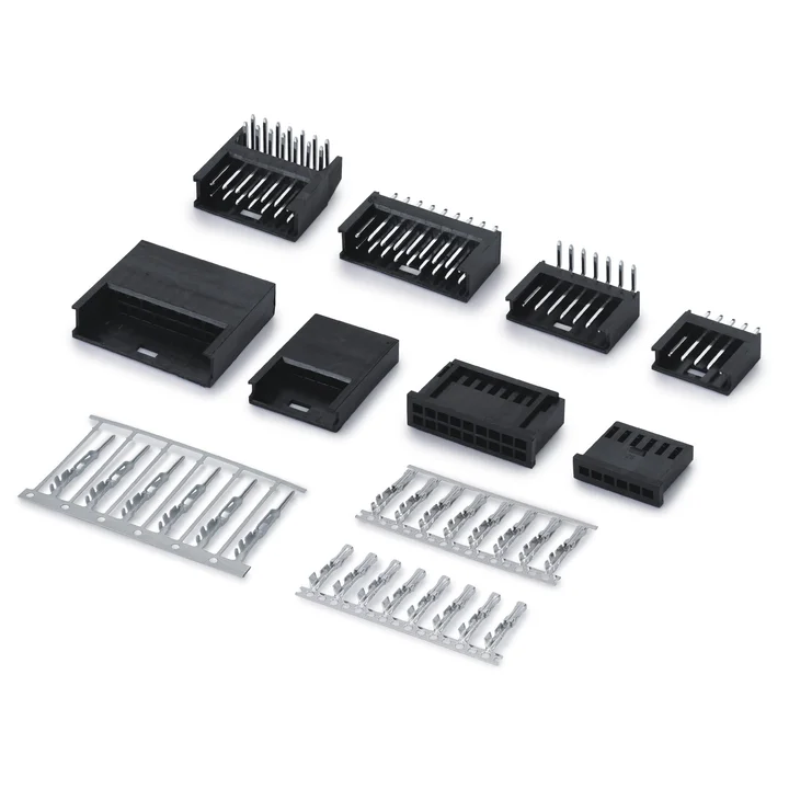
Separate male and female housings are documented in single-row and dual-row layouts, together with multiple through-hole board profiles.
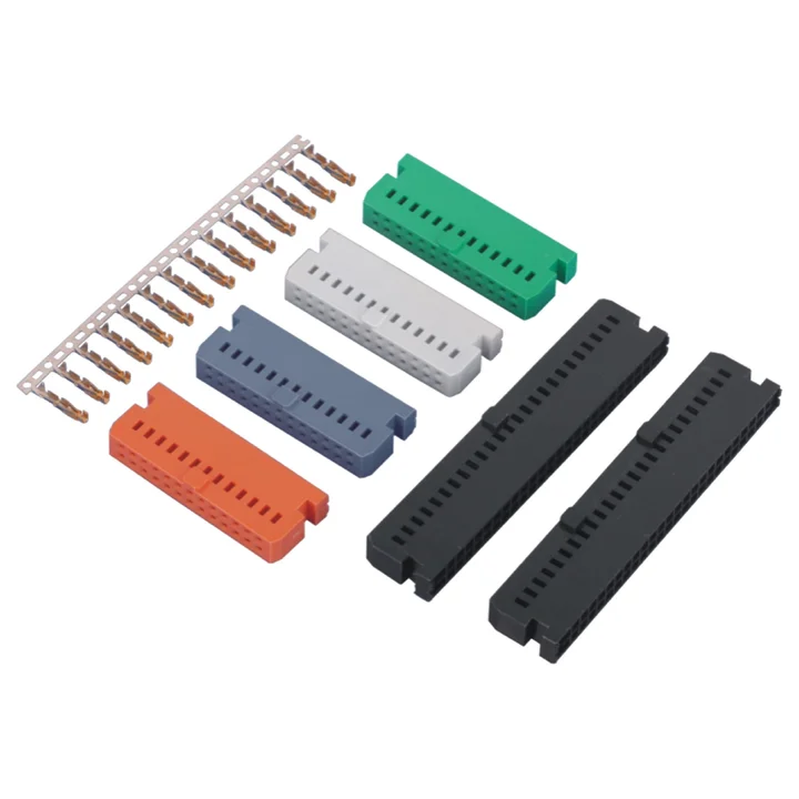
Dual-row wire-to-board connector system with crimp housings and ejector-latch board connectors.
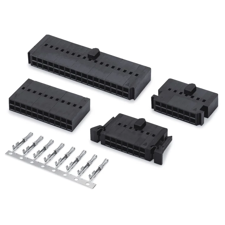
Black PBT housings have several latch, key and mounting profiles.
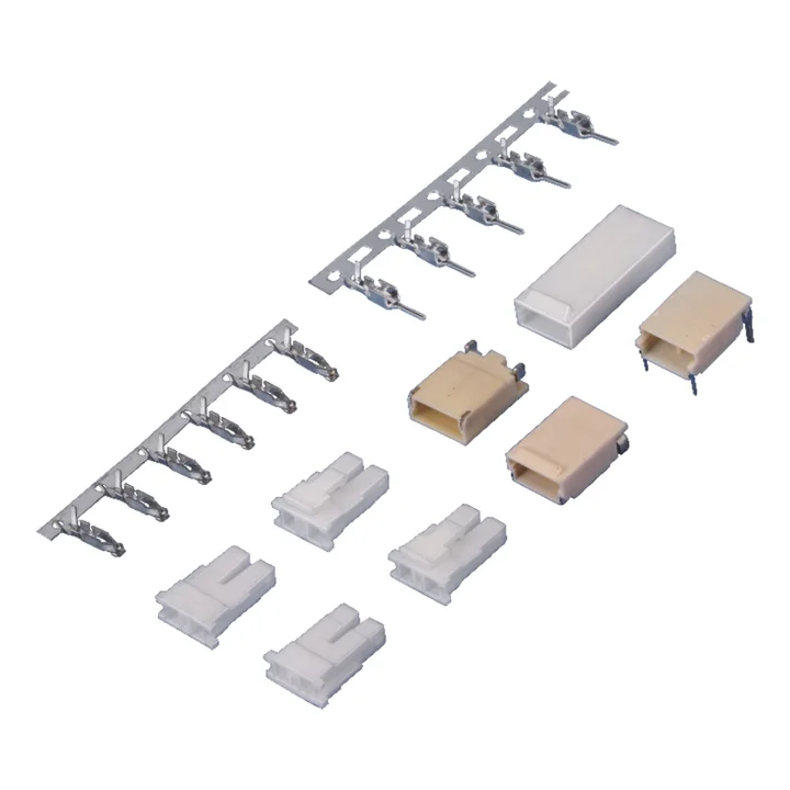
Natural PA66 male and female cable housings are documented with tin-plated phosphor-bronze terminals.
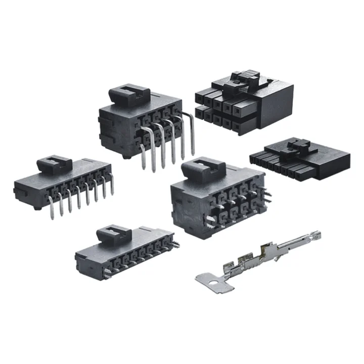
Black PA4T housings include standard and terminal-position-assurance profiles.
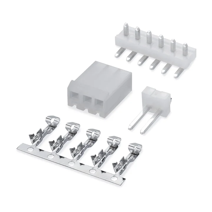
Natural PA66 housings are shown with straight and right-angle PA66 through-hole board profiles.
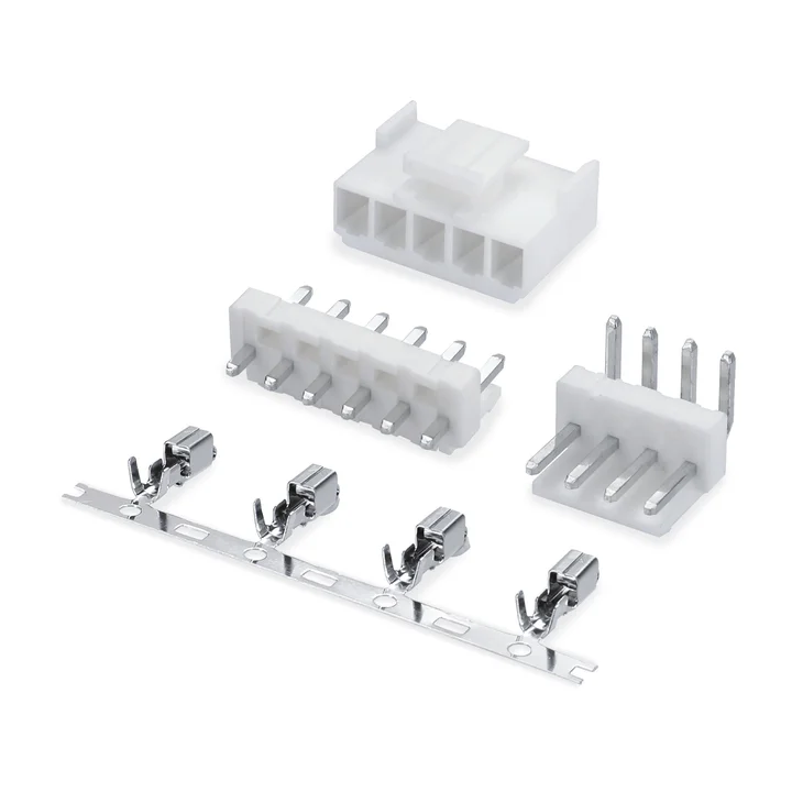
Single-row wire-to-board connector system with crimp housings and right-angle or vertical through-hole board connectors.
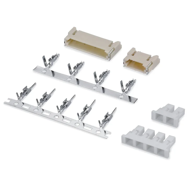
White PA66 male and female housings are documented with tin-plated phosphor-bronze terminals.
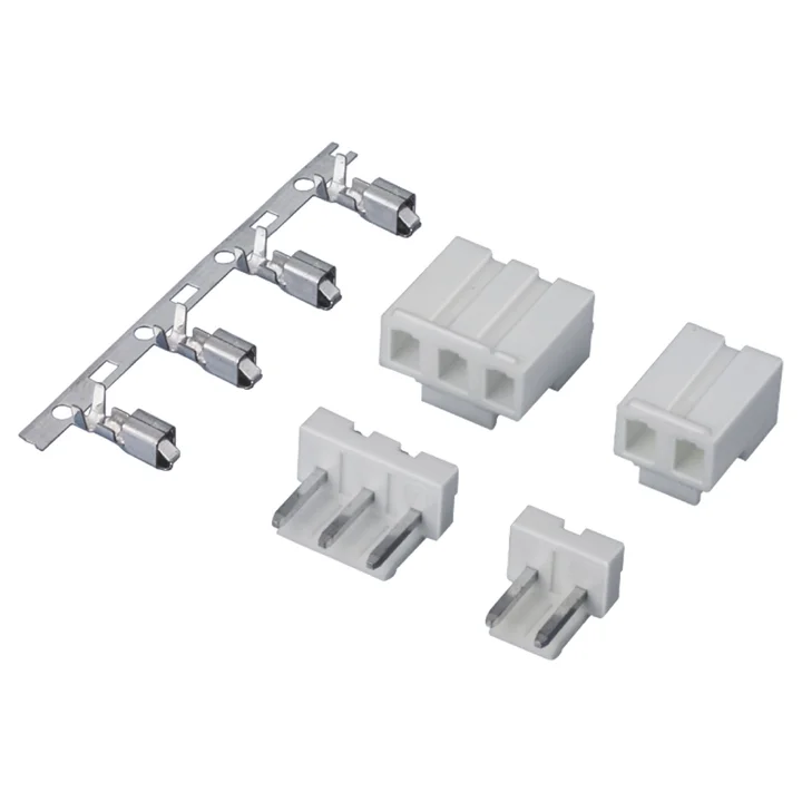
Natural PA66 housing, a tin-plated phosphor-bronze crimp terminal and a natural PA66 straight through-hole board profile are documented.
The reviewed housing specifies natural PA66.
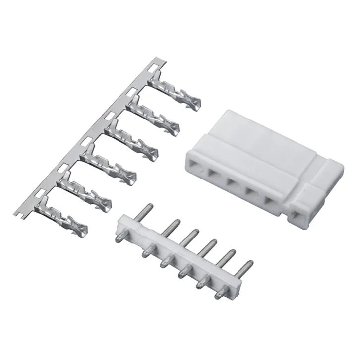
Construction details for this series are awaiting drawing confirmation.
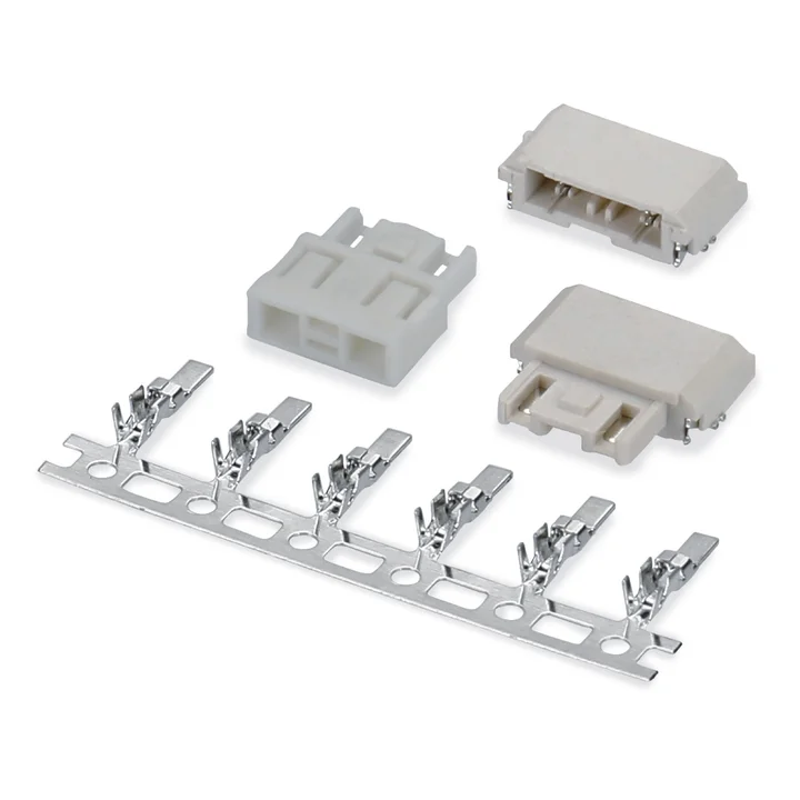
PBT housings with one- and two-position examples; the reviewed two-position surface-mount PCB pair specifies LCP housings and tin-plated phosphor-bronze contacts.
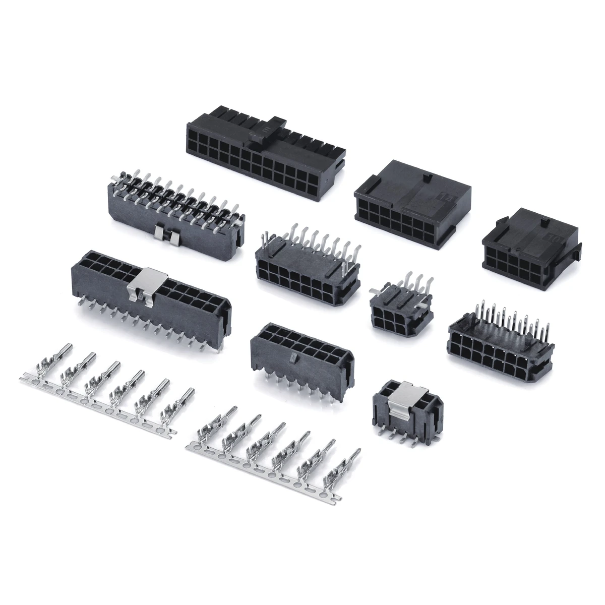
Single- and dual-row cable housings, crimp contacts, and THT or SMT board connectors for wire-to-wire and wire-to-board configurations.
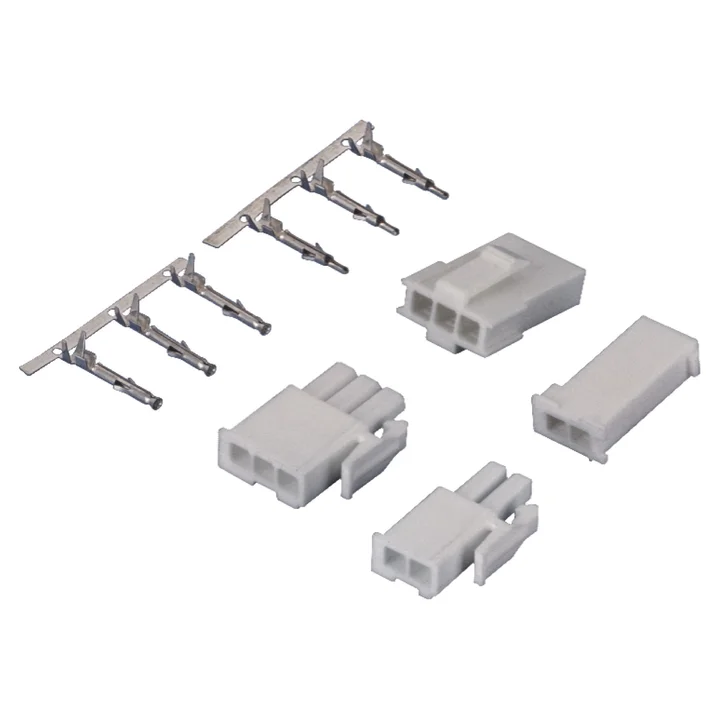
PA66 male and female housings include single- and multiple-row layouts.
PA66 single- and dual-row male and female housings are documented.
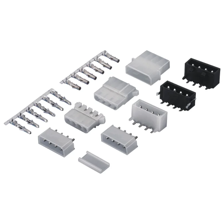
A four-position PA66 female housing and separate right-angle and straight through-hole PCB variants are documented.
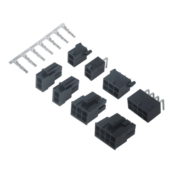
The matched drawings show straight and right-angle through-hole PCB connectors with LCP housings and tin-plated high-conductivity copper-alloy contacts.
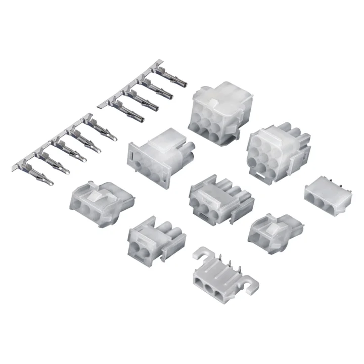
The reviewed single-row housing and PCB drawings specify 6.35 mm pitch.
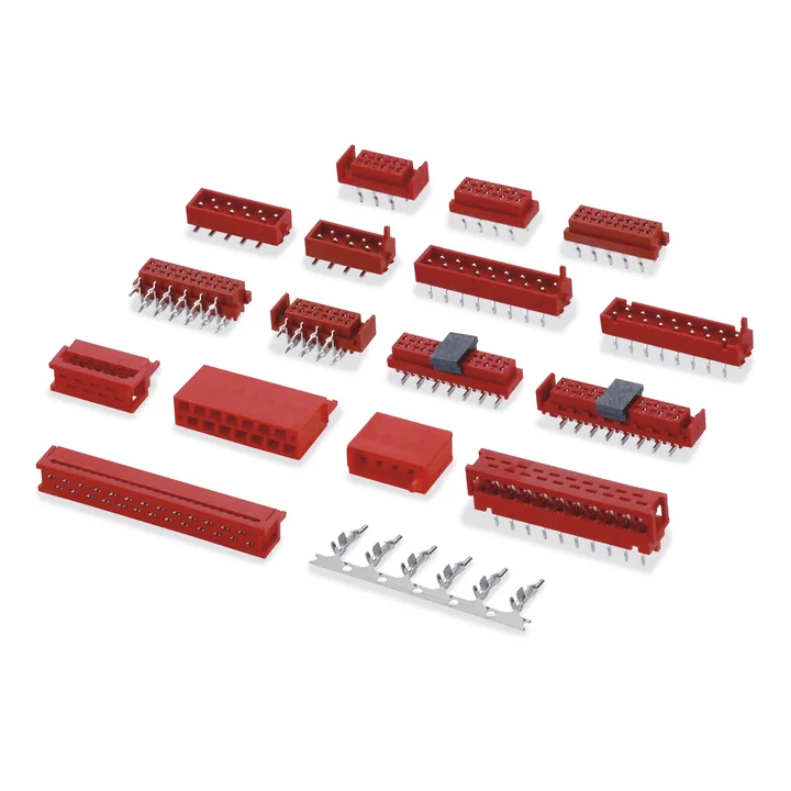
Dual-row PBT cable housings and separate PA9T PCB variants are documented.
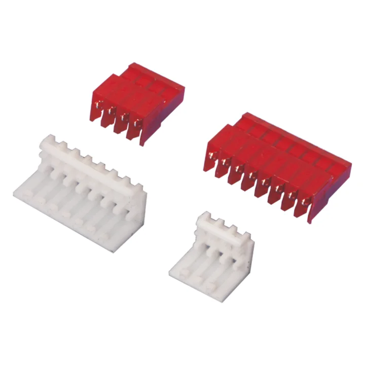
PA66 housings with phosphor-bronze terminals are shown in closed-end and feed-through forms, each with or without polarizing tabs.
PA66 housings with tin-plated brass contacts and a separate right-angle through-hole PCB construction are documented.
Plan the complete connection
These parts have different jobs. Check the selected drawings to define the complete mating connection.
Terminates the wire and fits into the selected housing. Confirm wire size and terminal construction.
Holds the terminated contacts in position. Confirm the circuit count, profile and mating features.
Mates with the cable-side housing and mounts to the PCB. Confirm the footprint, entry direction and clearance.
Housings, terminals and board connectors can be supplied separately or as a set. Connector samples are free; typical production MOQ is 1,000–5,000 pieces. Packaging can follow your requirements.
Define connector ends, wire lengths and pinout for a finished cable assembly.