
Single-row housing
The housing table lists 2–15 positions and specifies PA66 or PBT body options.
Choose an LDZY 1.50 mm single-row connection with 2–15 positions, crimp terminals and right-angle or vertical SMT board connectors. Review the complete mating set and the selected PCB footprint for your project.
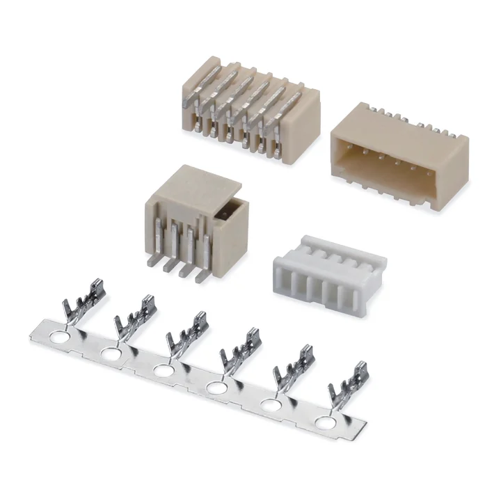
Connector construction
Select the housing, contacts and mating connector together. The available circuit counts and materials depend on the specific drawing, rather than one range covering every variant.
The housing table lists 2–15 positions and specifies PA66 or PBT body options.
Both board profile tables list 2–15 positions with tin-plated brass contacts. The drawings specify PA9T or LCP for one profile and PA6T for the other; confirm the selected footprint and body profile.
Specifications
Dimensions, materials and electrical ratings are configuration-specific. Refer to the corresponding technical drawing for part selection.
| Parameter | Specification |
|---|---|
| Pitch | 1.50 mm |
| Drawing-reference current | 3 A AC/DC |
| Drawing-reference voltage | 350 V AC/DC |
| Temperature range | -25 to +85 °C |
| Terminal wire range | 24–28 AWG; insulation outside diameter depends on the selected terminal finish |
Select the complete connection
A1501 is an LDZY 1.50 mm, single-row wire-to-board series. The public drawings list 2–15 positions for the housing and both SMT board profiles, with crimp terminals for 24–28 AWG wire. Start with the required position count and mating direction, then check the housing, terminal and board footprint together.
| Part | Drawing reference | What to confirm |
|---|---|---|
| Cable-side housing | Page 1: single row, 2–15 positions; PA66 or PBT body options. | Position count, housing profile, polarization and the selected terminal. |
| Crimp terminal | Page 2: 24–28 AWG; phosphor-bronze terminal with tin or gold-flash finish options. | Wire construction, insulation outside diameter, terminal finish and the applicable crimp specification. |
| Right-angle SMT board connector | Page 2: 2–15 positions; PA9T or LCP body options. | Side-entry mating space, solder-pad pattern, hold-down features and cable route. |
| Vertical SMT board connector | Page 3: 2–15 positions; PA6T body. | Top-entry mating height, PCB footprint, mounting features and enclosure clearance. |
Open the A1501 drawings and PDF below →
The material names in the drawings identify configuration options. They do not define a universal reflow profile or an application approval. Confirm the selected part and its processing requirements before releasing the PCB assembly process.
Prepare an A1501 inquiry
A1501 is available for supply. Housings, terminals and board connectors can be supplied separately or as a set. Standard connector samples are free, excluding freight. Typical production MOQ is 1,000–5,000 pieces per model or configuration; confirm your selected parts and quantities during quotation. Packaging can follow your requirements.
No series number yet? Send photos, drawings or a physical sample for selection assistance. Include views of the mating face, wire-entry side and counterpart where available. Appearance or measured pitch alone does not confirm a compatible pair.
No. Pitch is only one dimension. Check the housing profile, keying, latch, contact geometry and specified mating parts. A similar name or appearance from another supplier is not compatibility evidence.
Do not assume so. Compare the selected drawings, including pads and mounting features, then check mating access and the cable path inside your equipment before confirming the layout.
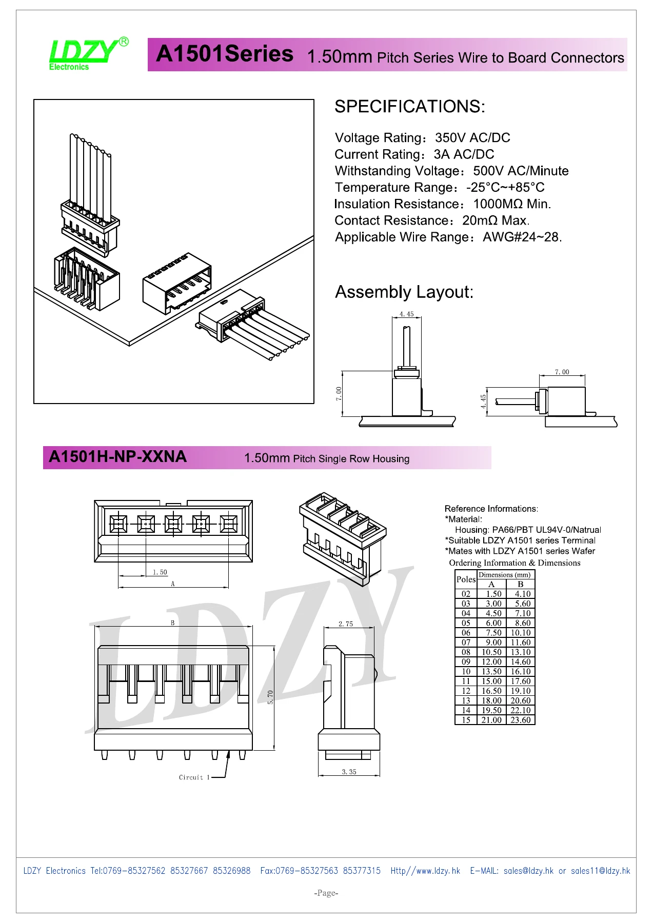
Drawings
View the drawings below or open the original PDF. Dimensions and specifications apply to the configuration and revision shown.
Engineering response
Send the released drawing, target configuration, quantities and any required documentation so the technical team can confirm the next step.