
Crimp housings
The drawings show single-row and dual-row PBT housings. Select the housing configuration and matching contact before defining the complete assembly.
A 1.0 mm wire-to-board connector system with crimp housings and SMT board connectors. Compare single-row and dual-row configurations, entry direction and the required mating pair.
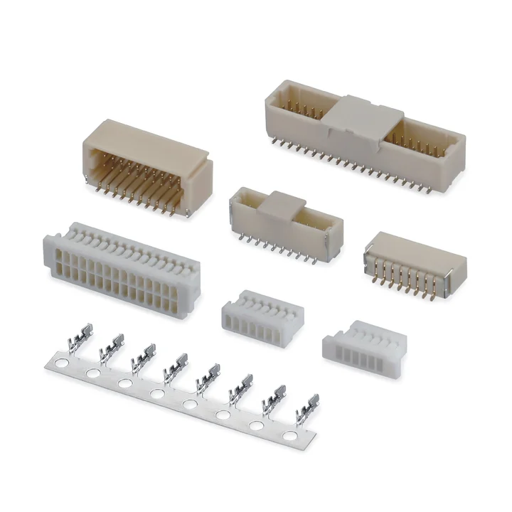
Connector construction
Select the housing, contacts and mating connector together. The available circuit counts and materials depend on the specific drawing, rather than one range covering every variant.
The drawings show single-row and dual-row PBT housings. Select the housing configuration and matching contact before defining the complete assembly.
The drawings include side-entry (90°) and top-entry (180°) board connectors with PA9T insulators. Circuit counts depend on the selected variant.
Specifications
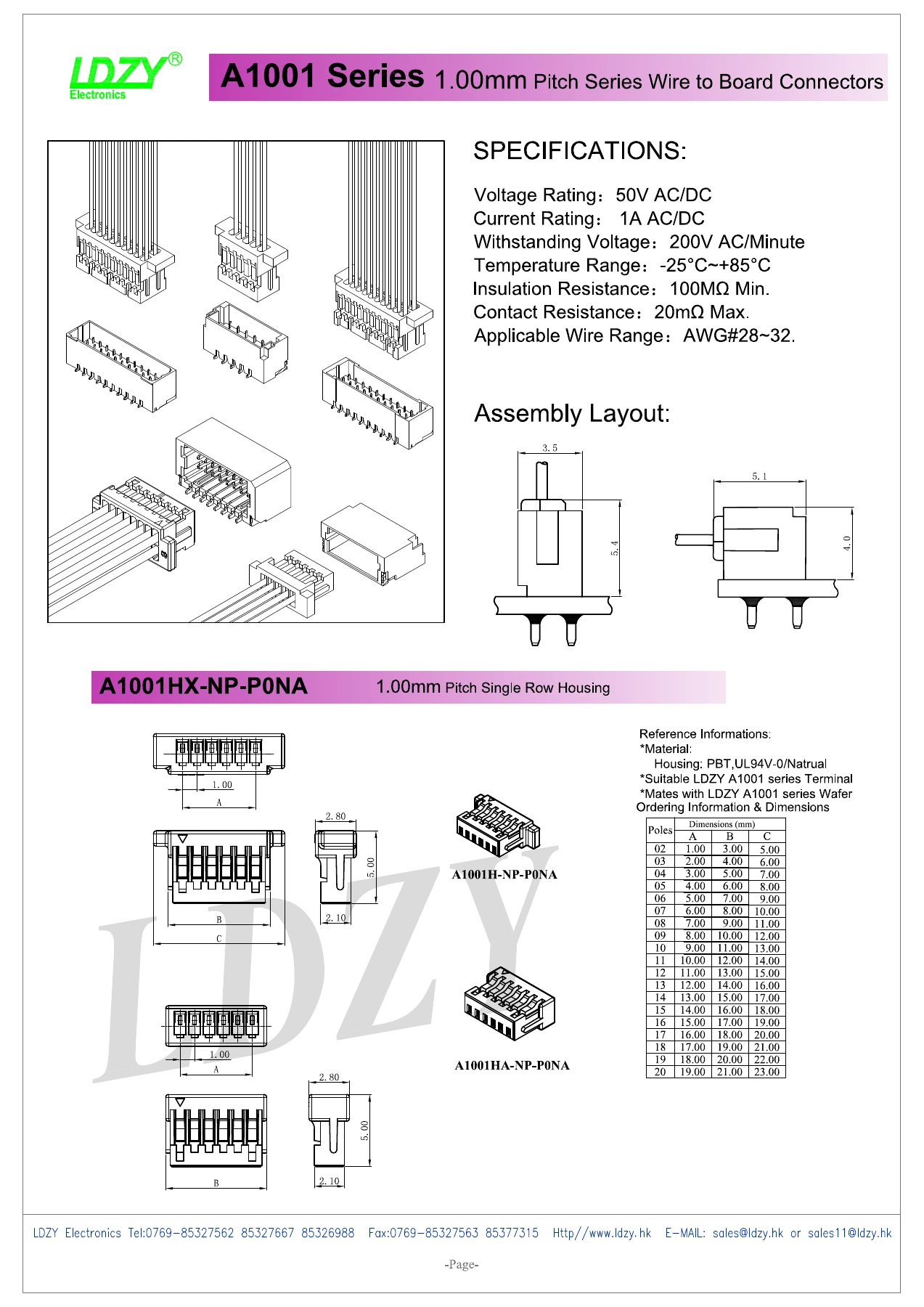
Dimensions, materials and electrical ratings are configuration-specific. Refer to the corresponding technical drawing for part selection.
| Parameter | Specification |
|---|---|
| Pitch | 1.00 mm |
| Current rating | 1 A AC/DC |
| Voltage rating | 50 V AC/DC |
| Crimp-terminal wire range | 28–32 AWG |
| Configuration | Single- and dual-row crimp housings and SMT board connectors; use the selected position table |
| PCB termination | SMT |
Drawings
View the drawings below or open the original PDF. Dimensions and specifications apply to the configuration and revision shown.
Engineering response
Send the released drawing, target configuration, quantities and any required documentation so the technical team can confirm the next step.