
Single- and dual-row THT
Straight and right-angle THT drawings use gold-flash phosphor-bronze contacts. The single-row right-angle body is PA6T; single-row straight is PBT. Dual-row versions list PBT or PA6T by configuration.
PH200 2.00 mm pin headers for PCB connections. Compare single- and dual-row THT, dual-row SMT and stacked SMT configurations before selecting dimensions.
Send your drawing and quantity. Response within one business day.
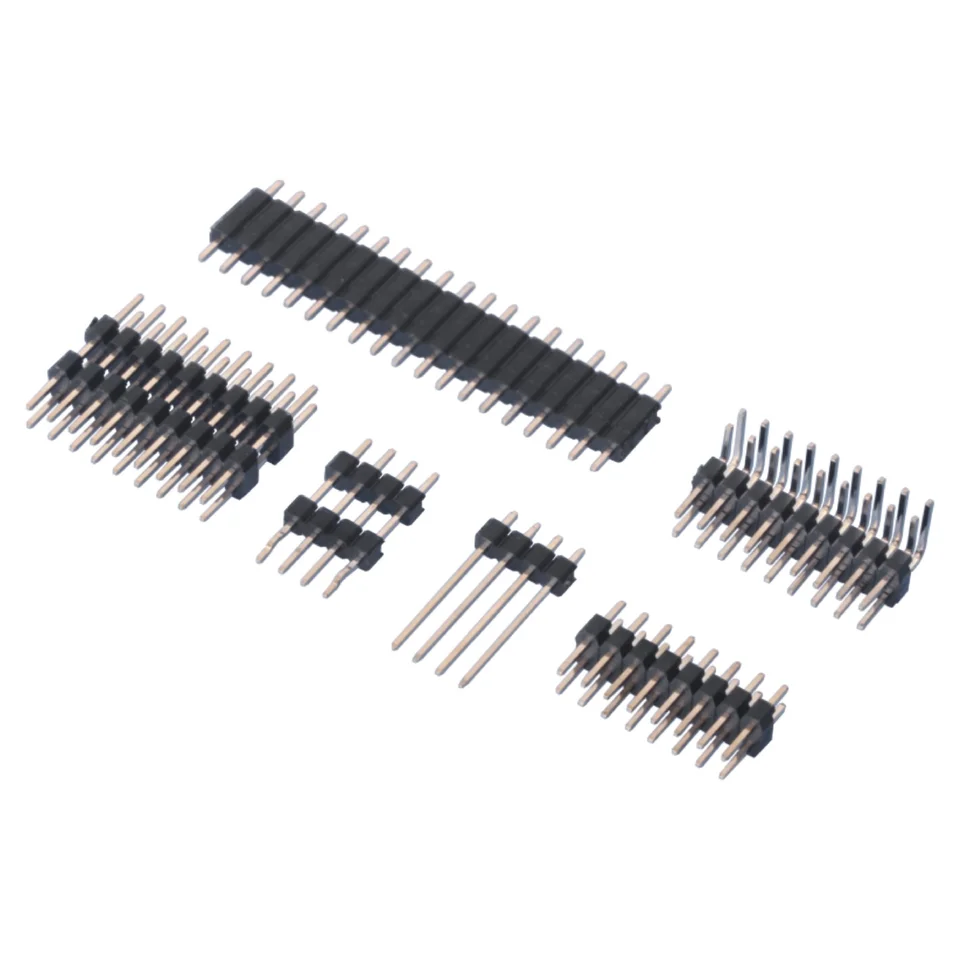
PH200 drawing reference
Use these drawing values for initial selection. Check the row layout, mounting and dimensions for the exact configuration before ordering; matching pitch alone does not establish mating compatibility.
| Parameter | Drawing value / scope |
|---|---|
| Series | PH200 |
| Pitch | 2.00 mm |
| Current rating | 2 A AC/DC |
| Voltage rating | 250 V AC/DC |
| Withstanding voltage | 1,000 V AC for 1 minute |
| Temperature range | −25°C to +85°C |
| Insulation resistance | 1,000 MΩ minimum |
| Contact resistance | 20 mΩ maximum |
| Single-row drawing tables | 2–40 positions; select the applicable configuration table |
| Dual-row drawing tables | 2 × 2 through 2 × 40 positions; not every mounting or height combination |
Configuration selection
The configurations below follow the supplied series drawings. They are not interchangeable options for every part. Include the required construction in your request.
Straight and right-angle THT drawings use gold-flash phosphor-bronze contacts. The single-row right-angle body is PA6T; single-row straight is PBT. Dual-row versions list PBT or PA6T by configuration.
The straight dual-row stacked SMT drawing specifies PBT or PA6T and gold-flash phosphor-bronze contacts. Review the spacing between bodies, mating-post length and solder-tail arrangement.
The straight dual-row SMT drawing lists PBT or PA6T with gold-flash phosphor-bronze contacts. Use its specific body dimensions and pad layout, not those of a through-hole version.
Drawings
View the drawings below or open the original PDF. Dimensions and specifications apply to the configuration and revision shown.
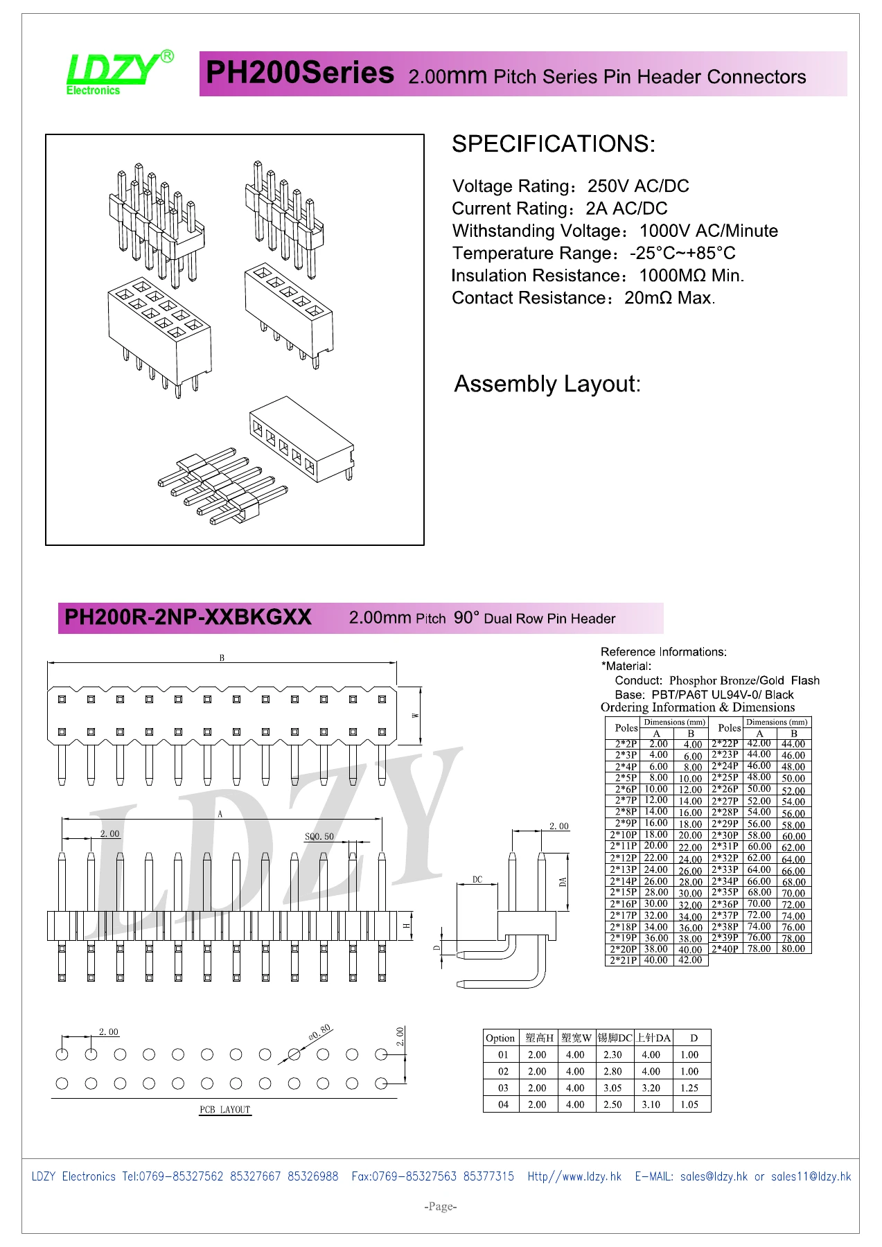
Drawing and quantity review
A dimensioned drawing, BOM or marked-up sketch helps identify the required header configuration.