
Choose a ribbon cable termination by matching the cable, contact system and required connection layout. IDC can terminate compatible ribbon conductors together; individual crimps allow separated wires to enter suitable housings; soldering connects prepared conductors to terminals designed for solder. No method is universally the strongest, cheapest or most suitable for every environment.
Compare the connection requirements first
| Method | Useful when | Confirm before selecting |
|---|---|---|
| IDC | A compatible ribbon and contact system support the required arrangement and mass termination. | Conductor pitch, size and construction, insulation, connector tooling, cover and strain relief. |
| Crimp | Separated conductors need individual routing, a changed pinout or suitable crimp-contact housings. | Wire and insulation range, strip length, terminal, crimp tooling and housing retention. |
| Solder | The selected interface has solder cups, tabs or other solderable terminations. | Wire preparation, soldering process, insulation clearance and support beyond the joint. |
For quotation, compare complete assemblies rather than the termination operation alone. Wire preparation, connector cost, tooling, inspection and production quantity all affect the result. A D-sub interface, for example, does not identify the cable termination method: the selected connector construction does.
IDC: match the contact to the cable construction
Insulation displacement contacts form an electrical connection by displacing insulation as the compatible conductor is seated. For ribbon mass termination, the alignment between cable conductors and contacts is essential. Cable conductor pitch and the mating connector's contact pitch are separate dimensions; do not assume they are identical.
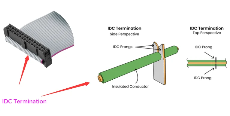
Review the specified wire size, solid or stranded construction, insulation dimensions and material. Use the connector's application instructions for tooling, seating and any required strain-relief accessory. The cable fitting physically into a connector is not proof of compatibility.
IDC is not automatically unsuitable for vibration. Suitability depends on the specific connector, retention features, cable support, installation and qualification requirements. Conversely, a correctly seated IDC connector alone does not prove the complete assembly meets an application's vibration requirement.
Crimping: route and terminate individual conductors
Where the cable construction permits separation, ribbon ends can be split into individual wires, stripped and terminated with compatible crimp contacts. This supports breakouts, different end arrangements or a non-sequential pinout. Define the split length and support so movement is not concentrated where the ribbon separates.
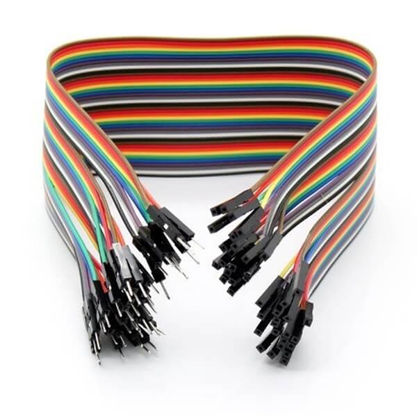
A crimp must match the conductor, insulation and specified tool setup. Check the conductor crimp and insulation support separately; terminal seating and locking in the housing are additional checks. Use the contact manufacturer's acceptance requirements rather than a generic pull-force value.
Soldering: control the joint and support the wire
Solder termination suits connectors and terminals designed for it. Preparation and process control matter: exposed strands, bridging, insulation damage or solder wicking along a flexible conductor can compromise the result. Provide mechanical support beyond the joint rather than asking the solder joint to carry cable loads.
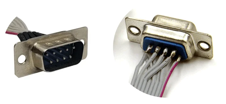
Soldering is not limited to prototypes, and it is not automatically more reliable than a qualified crimp or IDC connection. Select the actual connector system, manufacturing process and acceptance criteria for the project.
Specify the finished assembly, not just the method
- Both ends: connector identification, mating face view, pin numbering and exit direction.
- Cable: conductor count, wire size, conductor pitch, insulation and length references.
- Connection map: every contact-to-contact connection, unused positions and any split or branched section.
- Protection: covers, strain relief, sleeves and shield connections where applicable.
- Inspection: electrical checks and agreed mechanical or appearance criteria.
Mixed terminations are possible when the chosen components and cable support them. For example, one end may use IDC while separated conductors at the other end use suitable crimp contacts or solder terminations. Confirm the whole pinout and mechanical layout rather than assuming a straight-through connection.
From selection to a custom assembly
LDZY builds custom ribbon cable assemblies from drawings or reviewed requirements. Send your existing drawing or sample details, cable routing and order quantities. We can review the termination arrangement before sampling. Use the testing guide to define what acceptance should cover, then request a quotation.
Does a ribbon cable's stripe define the pinout?
The stripe identifies one edge conductor. The drawing must still specify its connection at each end, including the connector viewing direction.
Are ribbon cables and FFC interchangeable?
No. A similar flat shape does not establish the same conductor construction or termination system. Select the cable and mating connector as a compatible combination.
Technical references: TE: IDC ribbon cable construction; Samtec: IDC cable systems and mating options. These describe particular supplier systems, not interchangeability with LDZY products.