
A ribbon cable assembly should be checked against its approved drawing, not just for whether a meter beeps. The useful starting point is a defined pin-to-pin map, connector orientation and set of acceptance criteria. Electrical checks establish the connections tested; they do not by themselves prove mechanical retention, signal performance or service life.
Start with the drawing and connector viewing direction
Identify both connectors, their pin numbers, the drawing revision and whether each view looks into the mating face or the wire-entry side. A mirrored connector view can produce a cable that looks correct but connects the wrong circuits. A stripe on the ribbon helps identify a conductor; it does not replace the approved pinout.
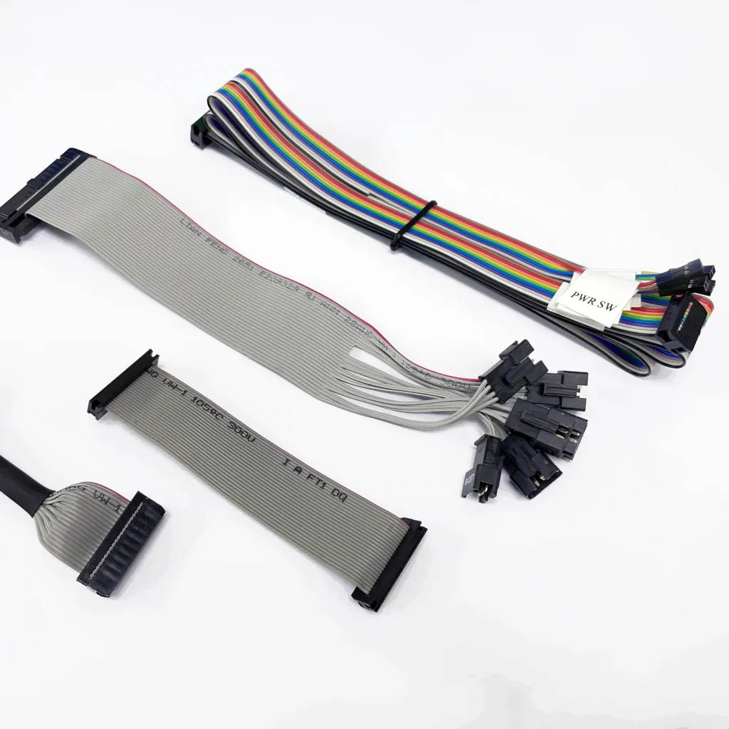
- List every required connection, intentional jumper, unused contact and shield connection.
- Define cable length and its measurement reference, orientation, labels and tolerances.
- Agree the test method, acceptance limits and inspection frequency for each requirement.
- Confirm fixtures and the test program against the drawing before using a sample as a reference. Learning a sample alone can reproduce its wiring error.
Check continuity, shorts and the complete pinout
| Check | What it establishes | What to specify |
|---|---|---|
| Continuity / opens | Each intended path is connected within the agreed resistance limit. | Expected networks, test current or method, and maximum connection resistance. |
| Short circuits | Connections that should be isolated are not unintentionally joined within the test limits. | All isolated networks, including unused contacts and shields where applicable. |
| Pinout / miswires | Each contact reaches its designated destination, rather than simply any contact at the opposite end. | Numbered connector views and a point-to-point map. |
| Insulation resistance / dielectric withstand | The specified isolation requirement under a defined test condition. | Whether required, test voltage, duration, limits and component compatibility. Never assume a universal setting. |
Use equipment and fixtures appropriate to the assembly. For a basic sample check with a multimeter, disconnect the cable from powered equipment, follow the approved map, check intended paths and check isolation between separate networks. A continuity beep is a coarse indication; it is not a substitute for a specified resistance measurement or a complete production test program.
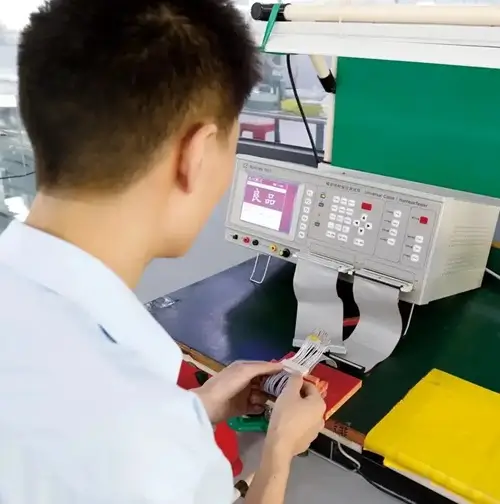
Inspect dimensions, connector seating and cable support
Look for misaligned ribbon conductors, damaged insulation, incomplete covers or latches, exposed strands and incorrect labels. Check the connector exit direction and the cable length at the drawing references. Where an IDC strain-relief accessory is specified, check its installation against the connector instructions.
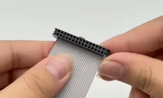
Terminal retention, crimp pull force, connector mating retention and whole-cable pull tests assess different load paths. Identify which one is required and how the part is held. Destructive or potentially damaging tests need an agreed sample plan; passing an electrical check does not establish the result of those tests.
Separate routine checks from application qualification
Signal-integrity, repeated-flex, vibration and environmental tests answer application-specific questions. Define the setup, loading, duration or cycle requirement and pass/fail criteria before requesting them. A cable that passes continuity can still fail to meet a system's signal or movement requirements.
For shielded assemblies, a verified shield connection is useful, but it does not establish EMC performance in the equipment. See the ribbon cable shielding guide for the additional design inputs.
Define acceptance before sampling and production
LDZY performs 100% electrical testing, with periodic visual and terminal-retention checks. Share any additional acceptance requirements during quotation so their scope and method can be reviewed. A shipment inspection report is available on request. Identify any required inspection items and report format during quotation so the documentation scope can be confirmed before placing the order.
- Drawing revision, connector views and pinout.
- Electrical limits and any special isolation requirements.
- Dimensions, labels, appearance and mechanical criteria.
- Inspection frequency and any required documentation.
- Customer equipment tests needed before sample approval.
Review our custom ribbon cable assemblies or use the RFQ checklist to prepare a drawing-based inquiry.
Common questions
Does continuity testing prove that a cable will work in my equipment?
No. It checks specified electrical connections. Functional operation, signal performance and fit in the equipment require the relevant application checks.
Should every cable receive a high-voltage test?
The need and settings depend on the approved specification and connected components. Do not apply an arbitrary voltage or treat a higher test voltage as automatically better.
Technical reference: Cirris: setting resistance test thresholds. Equipment guidance explains test principles; it does not identify the equipment used by LDZY.