
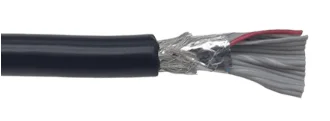
A shielded ribbon cable uses a conductive layer around its conductors to help control electromagnetic coupling with its surroundings. The result depends on the cable structure, shield connections, routing and equipment design. Specifying only “shielded cable” leaves important parts of the assembly undefined.
What shielding can and cannot do
An overall shield can help reduce coupling between the cable and external interference sources, and can help control emissions from the cable. It does not individually isolate adjacent conductors inside the ribbon. Their coupling still depends on signal arrangement, return paths, spacing, cable length and the connected circuits.
A conductive shield is not a waterproof seal. Moisture, dust, abrasion and chemical resistance depend on the jacket, connector, seals and complete installation. Nor does the presence of a shield establish a data rate, an EMC pass result or a required service life.
Foil, braid and combined constructions
| Construction | Design considerations | Details to put on the drawing |
|---|---|---|
| Foil | Can provide broad coverage with a thin conductive layer. Overlap, handling and termination affect the installed result. | Shield material and layer arrangement, overlap, continuity and the intended drain-wire connection where used. |
| Braid | A woven conductive shield has openings; coverage, flexibility and termination depend on its construction. | Braid construction or approved cable reference, exposed length and connector or chassis connection. |
| Foil and braid | Combines layers but also changes thickness, stiffness and termination work. More layers alone do not establish a performance rating. | Which layers connect at each end and how the full assembly fits the available space. |
These are general construction options, not a promise that every material combination is appropriate for your design. Confirm the cable construction and termination details for the specific project.
Shield termination and grounding belong in the design
Show the shield connection at each end: connector shell, designated contact, chassis attachment or an intentionally isolated end. Identify any drain wire and its destination separately from the signal return conductors. A drain wire provides a practical connection to a shield in some cable constructions; its continuity does not prove high-frequency shielding performance.
There is no universal rule to connect every shield at one end or at both ends. The arrangement depends on the interface, interference frequencies, equipment bonding and potential differences between connection points. At higher frequencies, connection geometry and inductance matter; a long exposed connection can compromise the intended shield path. The equipment designer should define the required bonding arrangement.
Review return paths, routing and cable movement
Adding an outer shield is not a substitute for reviewing the signal and return layout. Identify sensitive signals and their return paths, switching or motor wiring nearby, cable length and the position of chassis openings. Keep installation constraints visible in the assembly drawing rather than leaving the supplier to infer them from the cable alone.
For moving cables, define bend location, available radius, motion and required life. Neither braid nor foil should be assumed suitable for unrestricted repeated flexing. Select a construction intended for the motion and validate it under the specified conditions.
What to send for a shielded ribbon cable inquiry
- Connection drawing with pin numbering and connector viewing direction.
- Cable length, conductor count, wire size and available routing space.
- Signal types and relevant operating requirements, together with nearby interference sources.
- Required shield construction and connections at both ends, including drain wires and exposed lengths.
- Fixed installation or movement, bend constraints and environmental requirements.
- Electrical inspection requirements and any equipment-level EMC or signal validation needed.
If the shield arrangement is undecided, identify it as a design question before sampling. LDZY follows the customer drawing for shield construction, drain wires and grounding terminations in a custom ribbon cable project. Confirm these details before sampling so the assembly matches the intended equipment connections.
Inspect the connection; validate the system separately
Where required by the drawing, inspection can check shield termination, exposed lengths and specified electrical connections. A continuity result establishes the tested connection, not shielding effectiveness across a frequency range. EMC and signal-performance acceptance need their own defined setup and criteria.
See the ribbon cable testing guide and RFQ checklist to separate assembly inspection from application validation.
Does an overall shield eliminate crosstalk?
No. Adjacent conductors remain inside the same shield. Review their signal and return arrangement and validate the relevant electrical performance.
Is a drain wire a protective earth conductor?
Do not assume so. Protective earthing has its own design and safety requirements; a shield drain connection is not automatically suitable for that function.
Technical references: Analog Devices: hardware design and shielding; Belden: shield connections and ground loops. Apply the principles to the actual equipment design.